Range Rover 2. Electrical Manual - part 221
TRAILER AUXILIARY SOCKET
P1
6
CIRCUIT DIAGRAM
REV: 08/99
8
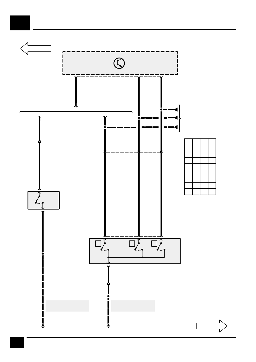
Z238
Body Electrical
Control Module
(BECM)
2
C0167
9
18
C1287
Automatic
Transmission
Manual
Transmission
13
C0746
0
1
X157
Reverse Switch
S551
E1355
UP
UG
S608
S609
S610
UB
6
C0244
0
[1]
X
1
0
[2]
Y
2
0
[3]
Z
3
C0244
GN
B
BS
S607
E0808
C0989
1
C0167
See Ground
Distribution
See Ground
Distribution
X294
Gear Box Position
Switch
[1]
X Switch
[2]
Y Switch
[3]
Z Switch
P
0
1
1
R
0
0
1
N
1
0
1
D
1
0
0
3
0
0
0
2
0
1
0
1
1
1
0
Z*
1
1
1
X
Y
Z
Automatic
Gearbox
1 =
0 =
* =
Switch Open
Switch Closed
Fault
3
5
C0745
C0988
4
2
C0988
C0745