Range Rover 2. Electrical Manual - part 24
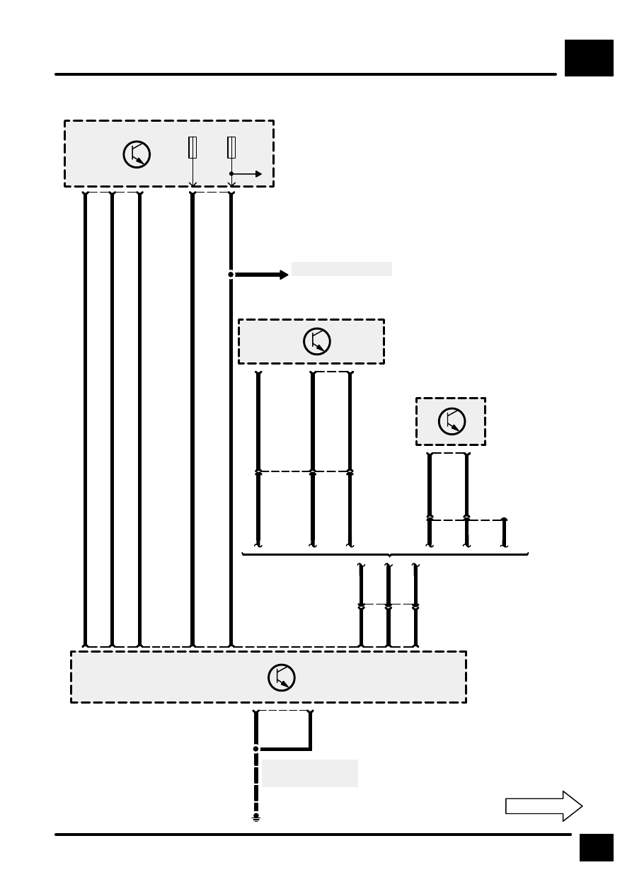
AUTOMATIC GEARBOX
B7
3
CIRCUIT DIAGRAM
Z238
Body Electrical
Control Module
(BECM)
11
S
3
12
K
51
1
C626
LG
15
30
F 3
5 A
7
PY
39
15
F 6
10 A
3
C625
W
1
S602
See Fuse Details
Z132
Engine Control
Module (ECM)
31
C507
SR
27
YO
29
C505
SP
6
C551
5
4
7
1
C659
S607
7
26
C601
See Ground Dis-
tribution
E621
Z255
Auto Gear Box
Control Unit
32
47
21
C601
Z132
Engine Control
Module (ECM)
43
SR
40
C572
YO
6
C551
5
4
SR
YO
SP
Not used
C581
B
C559
OY
C501
W
9
Diesel
Petrol