Range Rover 2. Electrical Manual - part 23
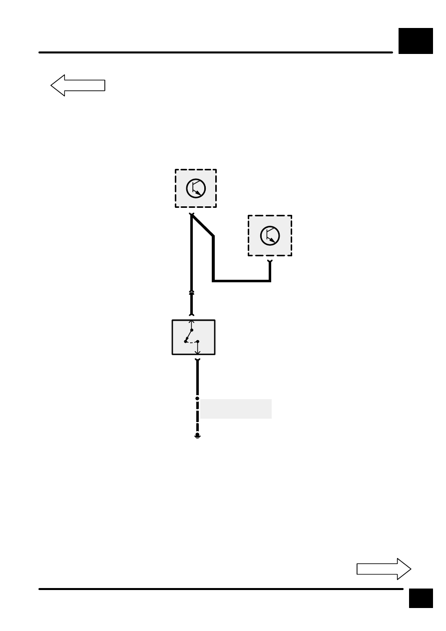
TRANSFER GEARBOX
B6
7
CIRCUIT DIAGRAM
18
C626
1
N
2
0
1
34
C603
E529
S551
N
B
See Ground Dis-
tribution
C660
11
C560
C563
C563
E574
Petrol
Diesel
Z238
Body Electrical
Control Module
(BECM)
X293
Neutral Switch
Z256
Transfer Gear
Box ECU
Manual Trans-
mission