Range Rover. Manual - part 286


  Index      Land Rover     Range Rover P38 - service manual 1995 year


Search            


Content   ..  284  285  286  287   ..


Range Rover. Manual - part 286


AIR CONDITIONING

1

DESCRIPTION AND OPERATION

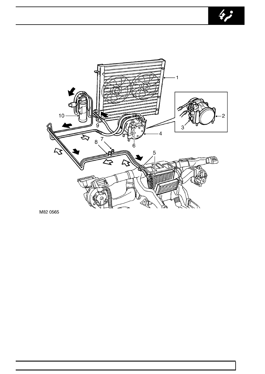
Refrigerant system components - V8 system shown

1. Condenser
2. Compressor (from 99MY)
3. Pressure relief valve
4. Compressor (up to 99MY)
5. Evaporator unit and expansion valve

6. Thermal cutout switch
7. High pressure servicing connection
8. Low pressure servicing connection
9. Pressure relief valve (up to 99MY)

10. Receiver/ Drier

82

AIR CONDITIONING

NEW RANGE ROVER

2

DESCRIPTION AND OPERATION

Control system components

11. Evaporator temperature sensor
12. ATC ECU
13. In-car temperature sensor
14. Ambient air temperature sensor (up to VIN

381430)

15. Single pressure switch

16. Dual pressure switch
17. Ambient air temperature sensor (from VIN

381431)

18. Sunlight sensor
19. Heater coolant temperature sensor

AIR CONDITIONING

3

DESCRIPTION AND OPERATION

Heating and distribution components

20. Heater unit
21. Heater matrix
22. Air to windscreen and front side window vents
23. Air to fascia centre vents, side vents, lap vent

(driver only) and rear face vents

24. Blower

25. Fresh/ Recirculated air servo
26. Air to front and rear footwells
27. LH temperature servo
28. Distribution servo
29. Fresh air inlet and pollen filter

82

AIR CONDITIONING

NEW RANGE ROVER

4

DESCRIPTION AND OPERATION

DESCRIPTION

The air conditioning system controls the temperature,
distribution and volume of air supplied to the vehicle
interior. The system is electronically controlled and
features automatic and manual modes of operation,
with separate temperature control of the LH and RH
air outlets. The automatic modes provide optimum
control of the system. The manual modes allow
individual functions of automatic operation to be
overridden to accommodate personal preferences.

The air conditioning system consists of a refrigerant
system and a control system. It also uses the same air
inlet housings and heater unit, and similar distribution
ducts, as the Heating and Ventilation system.

See

HEATING AND VENTILATION, Description and
operation.

Refrigerant system

The refrigerant system comprises four major units:

A compressor.

A condenser.

A receiver/ drier.

An evaporator and thermostatic expansion
valve.

The four units are interconnected by preformed
aluminium and flexible refrigerant pipes routed around
the perimeter of the engine compartment. A pressure
relief valve is incorporated to protect the refrigerant
system from unacceptably high pressure:

On vehicles up to 99MY, the pressure relief
valve is incorporated in the refrigerant pipe
between the compressor and the
condenser.

On vehicles from 99MY, the pressure relief
valve is incorporated into the refrigerant
outlet of the compressor.

Compressor

The compressor, a pump specially designed to raise
the pressure of the refrigerant, is mounted on the front
of the engine. The compressor is driven via an
electro-magnetic clutch by a single pulley drive belt
that also serves the other engine ancillaries.
Operation of the clutch is controlled by the ATC ECU.
On vehicles up to 99MY, the compressor incorporates
a thermal cutout switch in the electrical connection to
the clutch.

The compressor draws vaporized refrigerant from the
evaporator. It is compressed with a resulting rise in
temperature and passed on to the condenser as a hot,
high pressure vapour.

Condenser

The condenser is mounted directly in front of the
radiator. It consists of a refrigerant coil mounted in a
series of thin cooling fins to provide the maximum
heat transfer. Air flow across the condenser is induced
by vehicle movement and assisted by two electric fans
attached to the frame of the condenser. The
refrigerant high pressure vapour enters the condenser
inlet midway on the LH side. As the vapour passes
through the condenser coils the air flow, assisted by
the two fans, carries the latent heat away from the
condenser. This induces a change of state resulting in
the refrigerant condensing into a high pressure warm
liquid. From the condenser, the refrigerant continues
to the receiver/ drier.

Receiver/ Drier

This component acts as a reservoir and is used to
hold extra refrigerant until it is needed by the
evaporator. The drier within the receiver unit contains
a filter and dessicant (drying material) which absorb
moisture and prevent dessicant dust from being
carried with the refrigerant into the system.


Content   ..  284  285  286  287   ..