Range Rover. Manual - part 183


  Index      Land Rover     Range Rover P38 - service manual 1995 year


Search            


Content   ..  181  182  183  184   ..


Range Rover. Manual - part 183


ELECTRONIC AIR SUSPENSION

7

DESCRIPTION AND OPERATION

SYSTEM OPERATION

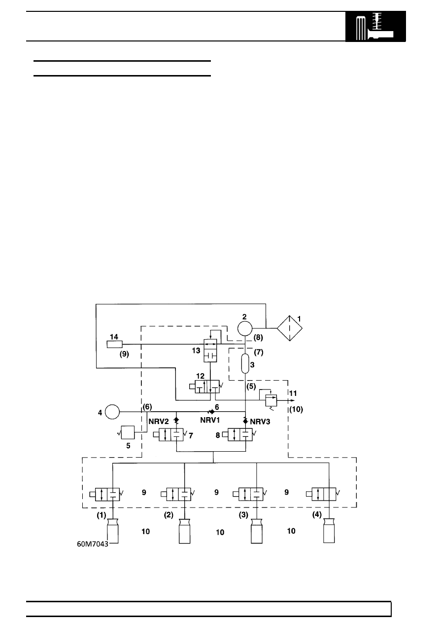
Numbers refer to pneumatic circuit diagram

Air is drawn through the inlet filter (1) to the
compressor (2), where it is compressed to 10

±

0,5

bar (145

±

7.25 lbf/in

2

).

Compressed air passes to the air dryer (3) where
moisture is removed as it flows through the dryer
dessicant. The dessicant in the lower portion of the
dryer becomes wet.

Dried air passes through a non-return valve NRV1 to
the reservoir (4).

The 3 non-return valves (6) ensure correct air flow.
They also prevent loss of spring pressure if total loss
of reservoir pressure occurs.

The pressure switch (5) maintains system pressure
between set limits by switching on and off the
compressor via an ECU controlled relay.

For air to be admitted to an air spring (10), the inlet
valve (7) must be energised together with the relevant
air spring solenoid valve (9).

For air to be exhausted from an air spring, the exhaust
valve (8) must be energised together with the relevant
air spring solenoid valve.

The solenoid diaphragm valve (12) ensures that all air
exhausted to atmosphere passses through the dryer.
Exhausted air passes vertically downwards through
the dryer. This action purges moisture from the
dessicant and regenerates the air dryer.

Air is finally exhausted through the system air
operated diaphragm valve (13) and to atmosphere
through a silencer (14) mounted below the valve
block.

60

FRONT SUSPENSION

NEW RANGE ROVER

8

DESCRIPTION AND OPERATION

FRONT SUSPENSION

Description

The front suspension design on the New Range Rover
allows maximum wheel travel and axle articulation,
providing good ground clearance without loss of
traction or directional stability.

Near constant ride frequency under all load conditions
is achieved by utilizing advancements in suspension
geometry complemented to control and operation of
the air suspension system.

See this section.

Front axle suspension

1. Radius arms
2. Panhard rod
3. Shock absorbers
4. Bump stops
5. Anti-roll bar
6. Air springs
7. Front axle

ELECTRONIC AIR SUSPENSION

9

DESCRIPTION AND OPERATION

Long front radius arms (1) are fitted to the front axle
(7) and provide maximum axle articulation which is
vital for off road performance. The radius arm,
comprising a forged steel link with twin front
mountings using ferrule rubber bushes, is secured to
fabricated mounting brackets welded to the front axle.
Flexible rubber bushes are used on a stem end joint
to secure the rear of the radius arm to a mounting on
the chassis cross member as shown in 60M7040. The
vehicle height sensors are also linked to the front
radius arms; for full details of the height settings.

See

this section.

A panhard rod (2), which ensures that the axle
remains centrally located, is fitted transversely and
also uses ferrule rubber bush mountings at both axle
and chassis locations. An anti-roll bar (5) is fitted to
the front axle to control body roll and directional
stability. Two rubber bearing bushes, with retaining
straps, secure the anti-roll bar to the front axle, while
ball jointed links, suspended from the chassis, support
the rear of the anti-roll bar.

Conventional telescopic shock absorbers (3), used to
control body movement, are secured to fabricated
towers which are welded to the chassis. The upper
fixing uses a single retaining bolt passing through a
flexible rubber bush. The lower fixing of the shock
absorber comprises of a stem type mounting with two
flexible rubber bushes and support washers secured
to an axle mounting by a single retaining nut. Cellular
foam bump stops (4) are fitted under the chassis
adjacent to the air springs (6) and prevent possible
damage that could occur should there be excessive
axle to chassis movement. Should there be a loss of
air pressure in the air springs the vehicle can still be
driven safely at a speed not exceeding 35 mph (56
km/h) with the bump stops resting on the axle,
although this will result in a hard ride. The loss of air
pressure should be investigated as soon as possible.
The bump stops are ’progressive’ and will reform from
a compressed state when the load is released.


Content   ..  181  182  183  184   ..