Range Rover. Manual - part 149


  Index      Land Rover     Range Rover P38 - service manual 1995 year


Search            


Content   ..  147  148  149  150   ..


Range Rover. Manual - part 149


TRANSFER BOX

13

REPAIR

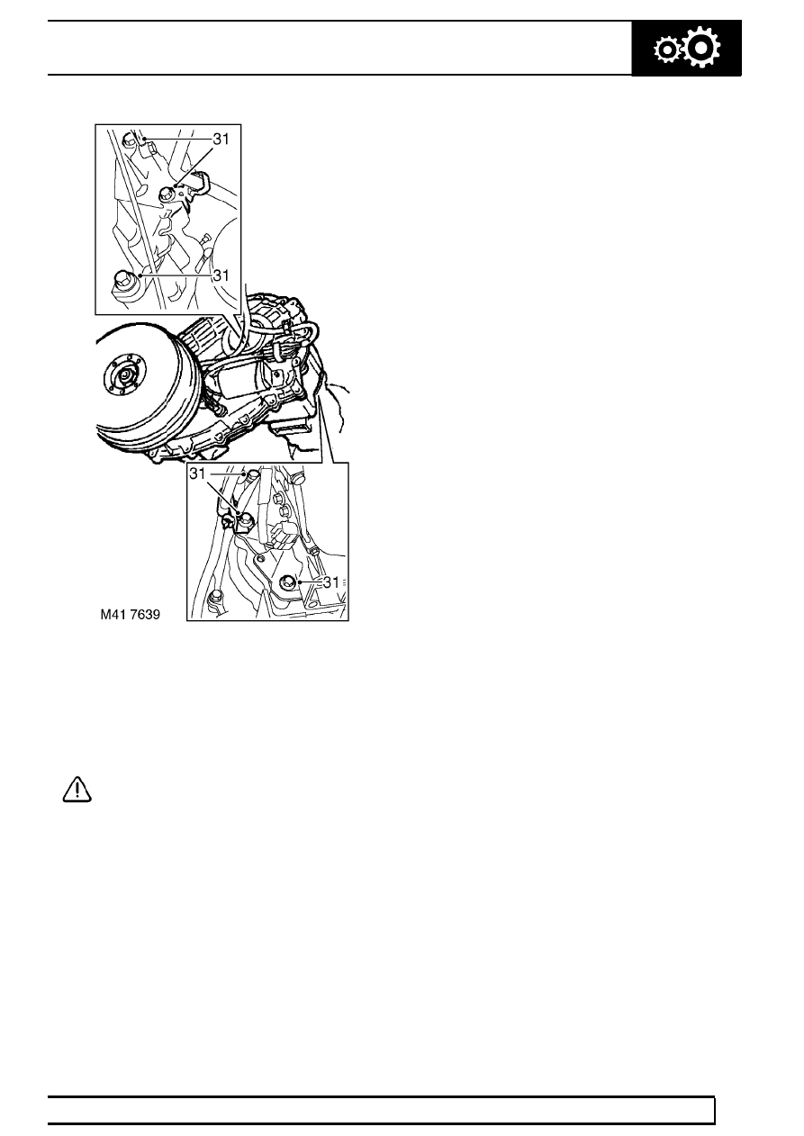
31. Remove 6 bolts securing transfer box to gearbox

and release 2 harness clip mounting brackets.

32. Adjust transmission lift as necessary, release

and remove transfer box.

33. Remove seal from transfer box casing using a

suitable lever.

CAUTION: Ensure seal location does not
become damaged as seal is levered from
casing.

34. Remove seal from gearbox casing using a

suitable lever.

Refit

35. Ensure seal location faces on gearbox are clean.
36. Lubricate oil seal lip with transmission fluid
37. Automatic models: Using LRT-44-001 fit seal

to gearbox casing.

38. Manual models: Using LRT-37-014 fit seal to

extension housing.

39. Ensure seal location faces on transfer box are

clean.

40. Lubricate oil seal lip with transfer box oil.
41. Using LRT-41-011 fit seal to transfer box.
42. Clean transfer and gearbox mating faces and

dowel and dowel holes.

43. Lubricate transfer box input shaft with

transmission fluid.

44. Raise transfer box on lift and adjust angle of lift

as necessary to align shafts.

45. Engage shafts and locate transfer box dowels to

gearbox.

46. Fit bolts securing transfer box to gearbox and

tighten to

45 Nm (33 lbf.ft). Ensure that the 2

harness clip mounting brackets are correctly
fitted when fitting bolts.

47. Secure harness to clips.
48. Align bracket securing fuel pipe and purge pipe

to transfer box and secure with bolt.

49. Connect multiplugs to High/Low motor and

output shaft speed sensor.

50. Connect 2 Lucars to transfer box fluid

temperature sensor.

51. Clean breather pipe bolt and banjo, fit new

sealing washers and tighten bolt to

15 Nm

(11 lbf.ft).

52. Align harness support bracket and gear selector

cable abutment bracket to gear box, and secure
with bolts.

53. Automatic models: Connect gear selector

cable trunnion to gearbox lever and secure with
split pin.

41

TRANSFER BOX

NEW RANGE ROVER

14

REPAIR

54. Adjust gear selector cable.

See AUTOMATIC

GEARBOX, Repair.

55. Raise transmission.
56. Clean propeller shaft and transfer box flanges.
57. Fit propeller shafts to transfer box flanges and

align marks.

58. Fit nuts to propeller shafts and tighten to

48 Nm

(35 lbf.ft).

59. Fit rear propeller shaft guard and secure with

bolts.

60. Fit and engage handbrake cable grommet into

transmission tunnel.

61. Fit transmission mounting assembly and tighten

bolts to

44 Nm (33 lbf.ft).

62. Support transmission under brake drum.
63. Lower lift and remove adaptor plate LRT-99-012

from lift.

64. Petrol models: Fit exhaust front pipe.

See

MANIFOLD AND EXHAUST SYSTEM, Repair.

65. Diesel models: Fit chassis crossmember.

See

CHASSIS AND BODY, Repair.

66. Connect handbrake cable to lever, fit clevis pin

and secure pin with clip.

67. Manual models: Position gear lever and tighten

bolts to

25 Nm (18 lbf.ft). Fit gaiter and gaiter

ring and secure with nuts.

68. Manual models: Fit centre console.

See

CHASSIS AND BODY, Repair.

69. Automatic models: Fit window switch pack.

See ELECTRICAL, Repair.

70. Position fan cowl and secure with clips.
71. Connect battery earth lead.
72. Fit battery cover and secure with fixings.
73. Fill transfer box with oil.

See SECTION 10,

Maintenance. See LUBRICANTS, FLUIDS
AND CAPACITIES, Information.

74. Fill gearbox with fluid.

See AUTOMATIC

GEARBOX, Repair.

44 - AUTOMATIC GEARBOX

CONTENTS

Page

ZF AUTO

DESCRIPTION AND OPERATION

AUTOMATIC TRANSMISSION - DESCRIPTION

4

................................................

OPERATION

19

......................................................................................................

ADJUSTMENT

SELECTOR CABLE

1

.............................................................................................

GEARBOX - DRAIN AND REFILL - FROM 99MY

1

...............................................

REPAIR

SELECTOR LEVER ASSEMBLY

1

.........................................................................

SELECTOR CABLE

3

.............................................................................................

SELECTOR INDICATOR & MODE SWITCH

4

.......................................................

SELECTOR POSITION SWITCH

5

.........................................................................

SEAL - SELECTOR SHAFT

6

.................................................................................

FLUID COOLER - V8 - UP TO 99MY

9

...................................................................

FLUID COOLER - V8 - FROM 99MY

10

.................................................................

FLUID COOLER - DIESEL

11

.................................................................................

AUTOMATIC GEARBOX - UP TO 99MY

12

...........................................................

AUTOMATIC GEARBOX - FROM 99MY

17

...........................................................

TORQUE CONVERTER OIL SEAL

22

...................................................................

HOUSING - TORQUE CONVERTER

23

................................................................

GASKET - INTERMEDIATE PLATE

24

..................................................................

INTERMEDIATE PLATE

26

....................................................................................

PUMP - FLUID

27

...................................................................................................

OUTPUT SHAFT SEAL

28

......................................................................................

GASKET - REAR EXTENSION HOUSING

29

........................................................

PARKING PAWL ASSEMBLY

29

............................................................................

FLUID PAN AND FILTER

30

...................................................................................

VALVE BODY ASSEMBLY

32

................................................................................

SEAL - VALVE BLOCK - SET

33

............................................................................

PRESSURE REGULATOR

34

................................................................................

LOCK UP SOLENOID VALVE (MV3)

35

.................................................................

SOLENOIDS - SHIFT CONTROL VALVES (MV1and 2)

35

....................................

HARNESS SOLENOID VALVES

36

.......................................................................

ELECTRONIC CONTROL UNIT

37

........................................................................


Content   ..  147  148  149  150   ..