Range Rover. Manual - part 132


  Index      Land Rover     Range Rover P38 - service manual 1995 year


Search            


Content   ..  130  131  132  133   ..


Range Rover. Manual - part 132


MANIFOLD AND EXHAUST SYSTEM

15

REPAIR

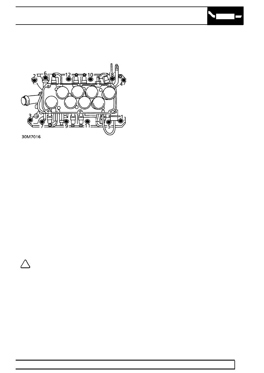
18. Using sequence shown, remove 12 bolts

securing inlet manifold to cylinder heads

19. Remove inlet manifold assembly.
20. Remove bolts and clamps securing manifold

gasket to cylinder block.

21. Remove inlet manifold gasket and discard.
22. Remove gasket seals and discard.

Refit

23. Ensure mating faces are clean.
24. Apply a thin bead of Loctite Superflex (black)

sealant to 4 notches between cylinder head and
block.

25. Position new gasket seals. Ensure ends engage

correctly in notches.

26. Fit new inlet manifold gasket.
27. Position manifold gasket clamps. Fit bolts and

tighten to

0.7 Nm (0.5 lbf.ft) .

28. With assistance to hold harness and ignition

coils aside, position inlet manifold assembly.

NOTE: When fitting inlet manifold bolts,
tighten in reverse of removal sequence.

29. Fit inlet manifold bolts. Initially tighten to

10 Nm

(7 lbf.ft)

30. Finally tighten bolts to

50 Nm (37 lbf.ft).

31. Tighten gasket clamp bolts to

17 Nm (13 lbf.ft).

32. Position RH injector harness and heater hose

bracket on inlet manifold. Secure with bolts.

33. Fit plenum chamber coolant hose to inlet

manifold. Secure with clip.

34. Connect 3 cooling hoses to inlet manifold.

Secure with clips.

35. Position ignition coil bracket on inlet manifold

studs. Secure with nuts. Tighten to

8 Nm

(6 lbf.ft).

36. Connect fuel feed pipe to fuel rail. Tighten to

16 Nm (12 lbf.ft).

37. Connect return hose to pressure regulator pipe.

Secure with clip.

38. Connect multiplugs to fuel injectors and fuel

temperature sensor.

39. Connect coolant temperature sensor and

temperature gauge sensor.

40. Connect purge and crankcase breather hose to

ram pipe housing.

41. Fit plenum chamber.

See FUEL SYSTEM,

Repair.

42. Refill cooling system.

See COOLING SYSTEM,

Repair.

43. Fit alternator.

See ELECTRICAL, Repair.

44. Start engine. Check for leaks around fuel rail and

injectors.

30

MANIFOLD AND EXHAUST SYSTEM

NEW RANGE ROVER

16

REPAIR

GASKET - INLET MANIFOLD - LOWER- FROM
99MY

Service repair no - 30.15.08

Remove

1. Remove RH and LH rocker cover gaskets.

See

ENGINE, Repair.

2. Disconnect multiplugs from coils.
3. Remove 2 bolts securing coils and remove coils.

4. Release leads from fuel rails and disconnect LH

and RH injector multiplugs.

5. Position absorbent cloth to catch any fuel

spillage and disconnect fuel pipe.

CAUTION: Plug the connections.

6. Remove auxiliary drive belt.

See ELECTRICAL,

Repair.

7. Remove 2 nuts securing leads to alternator and

release leads.

8. Release clip securing top hose to outlet pipe and

release hose.

9. Remove 2 bolts securing alternator and remove

alternator.

MANIFOLD AND EXHAUST SYSTEM

17

REPAIR

10. Disconnect multiplug from compressor.
11. Remove 4 bolts securing compressor to

mounting bracket and position compressor
aside.

12. Remove 2 bolts securing PAS pump to mounting

bracket and position aside.

13. Remove bolt securing jockey pulley to mounting

bracket and remove pulley.

14. Remove 4 bolts and one nut securing mounting

bracket and remove mounting bracket .

15. Remove 4 bolts securing top hose outlet pipe

and remove outlet pipe.

16. Remove and discard ’O’ ring.
17. Disconnect ECT sensor multiplug.

30

MANIFOLD AND EXHAUST SYSTEM

NEW RANGE ROVER

18

REPAIR

18. Using the sequence shown, remove 12 bolts

securing inlet manifold.

19. Remove inlet manifold assembly.

20. Remove 2 bolts securing manifold gasket

clamps and collect gasket clamps.

21. Remove inlet manifold gasket.
22. Remove gasket seals.

Refit

23. Clean RTV from head and block notches.
24. Clean mating faces of block, head and manifold.
25. Apply RTV silicone sealant in the four ’V’ shaped

notches between the ends of the cylinder head
and the cylinder block joint.

26. Fit new gasket seals, ensure ends engage

correctly in notches.

27. Fit new manifold gasket.
28. Position gasket clamps, fit bolts but do not

tighten at this stage.

29. Position inlet manifold assembly.

NOTE: When fitting inlet manifold bolts,
tighten in reverse of removal sequence.


Content   ..  130  131  132  133   ..