Range Rover. Manual - part 123


  Index      Land Rover     Range Rover P38 - service manual 1995 year


Search            


Content   ..  121  122  123  124   ..


Range Rover. Manual - part 123


LAND ROVER V8

7

DESCRIPTION AND OPERATION

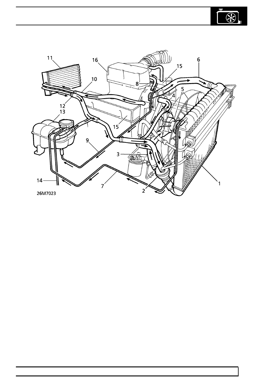
Cooling system coolant flow - up to 99MY

1. Radiator
2. Thermostat housing
3. Bottom hose
4. Bypass hose
5. Viscous fan and water pump
6. Radiator top hose
7. Radiator bleed pipe
8. Plenum chamber feed pipe

9. Plenum chamber bleed pipe

10. Heater feed hose
11. Heater matrix
12. Heater return hose
13. Expansion tank
14. Overflow/breather pipe
15. Cylinder banks
16. Plenum chamber

26

COOLING SYSTEM

NEW RANGE ROVER

8

DESCRIPTION AND OPERATION

Cooling system coolant flow - from 99MY

1. Heater matrix
2. Throttle housing
3. Throttle housing inlet hose
4. Throttle housing return pipe
5. Radiator top hose
6. Coolant pump
7. Manifold outlet pipe
8. Viscous fan
9. Radiator

10. Engine oil cooler
11. Gearbox oil cooler

12. Radiator bottom hose
13. Thermostat housing
14. By-pass hose
15. Coolant pump feed hose
16. Radiator bleed pipe
17. Overflow/breather pipe
18. Expansion tank
19. Pressure cap
20. Expansion hose
21. Heater inlet hose/pipe
22. Heater return hose/pipe

LAND ROVER V8

9

DESCRIPTION AND OPERATION

ENGINE COOLING - OPERATION

Coolant flow

Engine warm up - up to 99MY

When the engine is started from cold, the thermostat,
integral in the housing, prevents any coolant
circulation through the radiator by closing off the
supply from the radiator bottom hose.

During engine warm up, the water pump moves
coolant around the cylinders to the rear of the engine
block and along the galleries in both cylinder banks.
At the rear of the cylinder block the coolant rises
through a large port in both cylinder head/block joint
faces to the inlet manifold.

From the manifold, the coolant flow is divided between
the by-pass hose, the heater feed hose and the
plenum chamber feed pipe. The heater feed hose
supplies the heater matrix, located within the
distribution unit of the heating and ventilation system.
The coolant is then carried, via the heater return hose,
back to the thermostat housing to complete the cycle.

The heater matrix acts as a heat exchanger reducing
coolant temperature as it passes through the matrix.
With the thermostat closed and coolant flowing around
the by-pass circuit, the cooling system is operating at
maximum heater performance.

The plenum chamber is heated by a flow of coolant
through the feed pipe from the inlet manifold. A bleed
pipe returns the coolant from the plenum chamber
across the engine to the expansion tank.

Engine hot - up to 99MY

When normal engine running temperature is reached,
the main valve of the thermostat opens and a
secondary valve closes the bypass port. With the
thermostat open, coolant is circulated through the top
hose to the radiator.

The air flowing between the tubes cools the coolant as
it passes through the radiator. A controlled flow of the
lower temperature coolant is drawn from the base of
the radiator, through the bottom hose, by the water
pump and blended with hot coolant returning from the
heater matrix. Coolant circulation through cylinder
block and cylinder heads to the heater matrix and
plenum chamber remains the same.

Coolant is drawn from the base of the radiator,
through the bottom hose, by the water pump. Coolant
circulation through the cylinder block and cylinder
heads to the heater matrix and plenum chamber
remains the same.

An integral bleed pipe connects the top of the radiator
to the expansion tank and aids bleeding of air from the
coolant system. The expansion tank cap contains a
pressure valve which allows excessive pressure and
coolant to vent to the overflow pipe if the system has
been overfilled.

Engine warm up - from 99MY

When the engine is started from cold, the thermostat,
integral in the housing, prevents any coolant
circulation through the radiator by closing off the
supply from the radiator bottom hose.

During engine warm up, the water pump moves
coolant around the cylinders to the rear of the engine
block and along the galleries in both cylinder banks.
At the rear of the cylinder block the coolant rises
through a large port in both cylinder head/block joint
faces to the inlet manifold.

From the manifold, the coolant flow is divided between
the outlet pipe and the top hose by-pass connection to
the thermostat housing, the heater inlet pipe and hose
and the throttle housing inlet hose.

The heater inlet pipe and hose supply the heater
matrix, located within the distribution unit of the
heating and ventilation system. The coolant is then
carried, via the heater return hose and pipe, back to
the thermostat housing to complete the cycle.

The heater matrix acts as a heat exchanger reducing
coolant temperature as it passes through the matrix.
With the thermostat closed and coolant flowing around
the by-pass circuit, the cooling system is operating at
maximum heater performance.

The throttle housing inlet hose allows coolant to flow
from the inlet manifold to the plate attached to the
bottom of the throttle housing. A return pipe directs
coolant flow from the throttle housing to the expansion
tank.

26

COOLING SYSTEM

NEW RANGE ROVER

10

DESCRIPTION AND OPERATION

Engine hot - from 99MY

When normal engine running temperature is reached,
the main valve of the thermostat opens and a
secondary valve closes the bypass port from the top
hose. With the thermostat open, coolant is circulated
through the top hose to the radiator.

The air flowing between the tubes cools the coolant as
it passes through the radiator. A controlled flow of the
lower temperature coolant is drawn from the base of
the radiator, through the bottom hose, by the water
pump and blended with hot coolant returning from the
heater matrix. Coolant circulation through the cylinder
block and cylinder heads to the heater matrix and
throttle housing remains the same.

A bleed pipe connects the top of the radiator to the
expansion tank and aids bleeding of air from the
coolant system. The expansion tank cap contains a
pressure valve which allows excessive pressure and
coolant to vent to the overflow pipe if the system has
been overfilled.

Viscous fan

There are two main components of the viscous fan
drive : An input (drive) member consisting of a
threaded shaft passing through a bearing into the
clutch plate and secured to the water pump. An output
(driven) member comprises the main body to which
the fan attaches, with the temperature sensing
mechanism (bi-metal coil) and pump plates.

The fan drive only has to be engaged periodically,
between 5% and 10% of the time during normal
driving conditions, because usually the vehicle is
cooled by ram air.

A bi-metal coil senses air temperature behind the
radiator. When a pre-determined temperature is
reached, the coil opens a valve which allows fluid to
enter the drive area. Centrifugal force circulates the
fluid to the annular drive area. There are two sets of
annular grooves, one in the drive clutch and the other
in the drive body, a specific clearance being provided
between the two sets of grooves. When this clearance
is filled with viscous fluid a shearing action, caused by
the speed differential between the two drive
components, transmits torque to the fan. The fluid is
thrown to the outside of the unit by centrifugal force
from where it is then re-circulated to the reservoir via
the pump plate adjacent to the drive member.

If the engine speed is increased, the amount of slip
will also increase to limit the maximum fan speed.

Viscous unit disengaged (engine at normal
operating temperature)

1. Input (drive) member
2. Output (driven) member
3. Running clearance
4. Pump plate
5. Valve (closed)
6. Sensing mechanism (bi-metal coil)
7. Fluid seal
8. Bearing,input member
9. Fluid chamber

10. Fluid reservoir


Content   ..  121  122  123  124   ..