Range Rover. Manual - part 103


  Index      Land Rover     Range Rover P38 - service manual 1995 year


Search            


Content   ..  101  102  103  104   ..


Range Rover. Manual - part 103


LAND ROVER V8

13

REPAIR

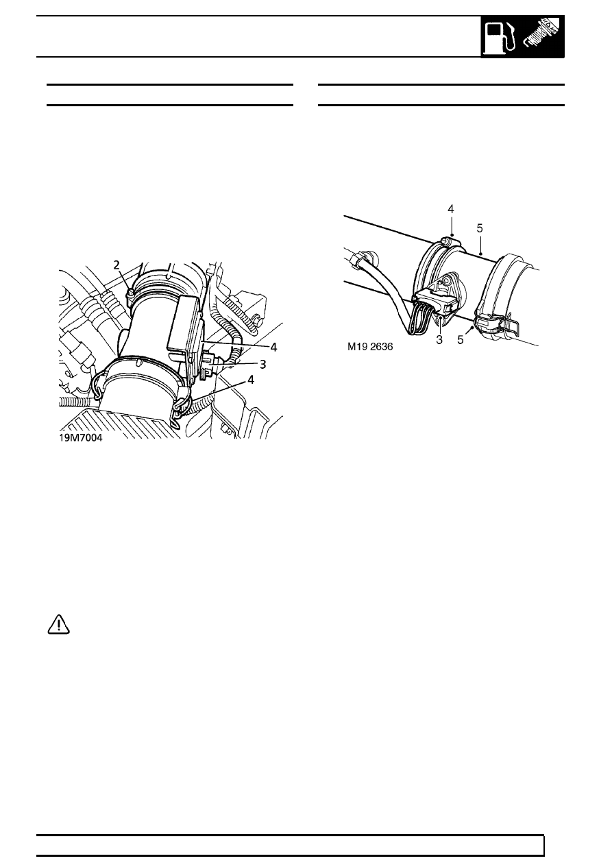
MASS AIR FLOW (MAF) SENSOR - up to 99MY

Service repair no - 19.22.25

Remove

1. Disconnect battery negative lead.
2. Loosen hose clip. Release intake hose from

MAF sensor.

3. Disconnect multiplug from MAF sensor.
4. Release 2 clips and remove MAF sensor from air

cleaner.

5. Collect ’O’ ring seal.

Refit

6. Ensure mating faces of air cleaner, MAF sensor

and intake hose are clean.

7. Fit ’O’ ring to MAF sensor.
8. Fit MAF Sensor to air cleaner. Secure with clips.
9. Connect multiplug to MAF sensor.

10. Connect intake hose. Secure with clip.

CAUTION: Failure to connect intake hose
securely will allow unmetered air to enter
the engine, causing running problems.

11. Reconnect battery negative lead.

MASS AIR FLOW (MAF) SENSOR - from 99MY

Service repair no - 19.22.25

Remove

1. Release fixings and remove battery cover.
2. Disconnect battery earth lead.

3. Disconnect multiplug from MAF sensor.
4. Loosen clip screw and release air intake hose

from MAF sensor.

5. Release 2 clips and remove sensor from air

cleaner.

Refit

6. Position sensor to air cleaner and secure clips.
7. Position air intake hose and tighten clip screw.
8. Connect multiplug.
9. Connect battery earth lead.

10. Fit battery cover and secure with fixings.

19

FUEL SYSTEM

NEW RANGE ROVER

14

REPAIR

FUEL RAIL AND INJECTORS - up to 99MY

Service repair no - 19.60.04 - Fuel Rail
Service repair no - 19.60.12 - Injectors

Remove

1. Disconnect battery negative lead.
2. Depressurise fuel system.

See this section.

3. Release plenum chamber and place aside.

See

this section.

4. Release purge hose, crankcase breather hose

and pressure regulator vacuum hose from ram
housing.

5. Remove 6 bolts securing ram housing to inlet

manifold.

6. Place small packing block on inlet manifold.

Lever between packing block and ram pipe
housing to break seal.

CAUTION: Do not lever against fuel rail.

7. Remove ram housing from 2 dowels.
8. Place cloth over inlet manifold to prevent ingress

of debris.

LAND ROVER V8

15

REPAIR

9. Disconnect 8 injector multiplugs.

10. Disconnect fuel temperature sensor multiplug.
11. Disconnect fuel feed hose from fuel rail.
12. Disconnect fuel return hose from pressure

regulator pipe.

NOTE: Advanced EVAPS vehicles have a
threaded connection to the return hose.

13. Remove 6 nuts securing fuel rail and ignition coil

bracket to inlet manifold.

14. Release ignition coil bracket from inlet manifold

studs. Place aside.

15. Release injectors from inlet manifold and remove

fuel rail assembly.
Do not carry out further dismantling if
component is removed for access only.

16. Remove 8 clips securing injectors to fuel rail.

Remove injectors.

17. Remove 2 ’O’ rings from each injector and

discard.

18. Remove 2 screws securing fuel pressure

regulator to fuel rail.

19. Release return pipe from clip. Remove pressure

regulator assembly.

20. Remove ’O’ ring from fuel pressure regulator and

discard.

19

FUEL SYSTEM

NEW RANGE ROVER

16

REPAIR

Refit

21. Ensure mating surfaces between inlet manifold

and ram pipe housing are clean.

22. Ensure all locations in fuel rail and inlet manifold

are clean.

23. Fit new ’O’ rings to injectors and fuel pressure

regulator.

24. Lubricate ’O’ rings with silicone grease.
25. Fit fuel pressure regulator to fuel rail. Secure

with bolts. Tighten to

10 Nm (7 lbf.ft)

26. Engage regulator return pipe in clip.
27. Fit injectors to fuel rail. Secure with clips.
28. Position fuel rail to inlet manifold. Engage

injectors, one bank at a time.

29. Position ignition coil bracket on inlet manifold

studs.

30. Secure ignition coil bracket and fuel rail to inlet

manifold with nuts. Tighten to

8 Nm (6 lbf.ft)

31. Connect return hose to pressure regulator pipe.

Secure with clip.

32. Connect fuel feed pipe to fuel rail. Tighten union

to

16 Nm (12 lbf.ft)

33. Connect multiplugs to fuel injectors and fuel

temperature sensor.

34. Remove cloth from inlet manifold.
35. Apply a thin, uniform coating of Loctite 577

sealant to mating face of inlet manifold.

36. Fit ram pipe housing to inlet manifold. Secure

with bolts. Tighten to

24 Nm (18 lbf.ft)

37. Connect purge hose, crankcase breather hose

and pressure regulator vacuum hose to ram pipe
housing.

38. Fit plenum chamber.

See this section.

39. Reconnect battery negative lead.
40. Start engine. Check for leaks around fuel rail and

injectors.

FUEL RAIL AND INJECTORS - from 99MY

Service repair no - 19.60.04 - Fuel Rail
Service repair no - 19.60.12 - Injectors

Remove

1. Remove upper inlet manifold gasket.

See

MANIFOLD AND EXHAUST SYSTEM, Repair.

2. Release HT leads from clips on rocker covers

and from spark plugs.

3. Disconnect multiplugs from coils.
4. Remove 2 lower coil fixing bolts and remove coil

assembly.

5. Position absorbent cloth beneath fuel pipe to

catch spillage.

6. Disconnect fuel feed hose from fuel rail

CAUTION: Plug the connections.

7. Release injector harness clips from fuel rail and

disconnect injector multiplugs.


Content   ..  101  102  103  104   ..