Range Rover. Manual - part 95


  Index      Land Rover     Range Rover P38 - service manual 1995 year


Search            


Content   ..  93  94  95  96   ..


Range Rover. Manual - part 95


LAND ROVER V8

47

DESCRIPTION AND OPERATION

If the sensor fails, the ECM uses a substitute software
routine that changes default value during warm up,
based on the signal from the inlet air temperature
sensor. When the software model reaches a coolant
temperature of 60

°

C (140

°

F) the ECM implements a

fixed default value of 85

°

C (185

°

F). The ECM coolant

model also forms part of the diagnostics that is
performed for detecting a temperature sensor fault, as
well as open and short circuit tests.
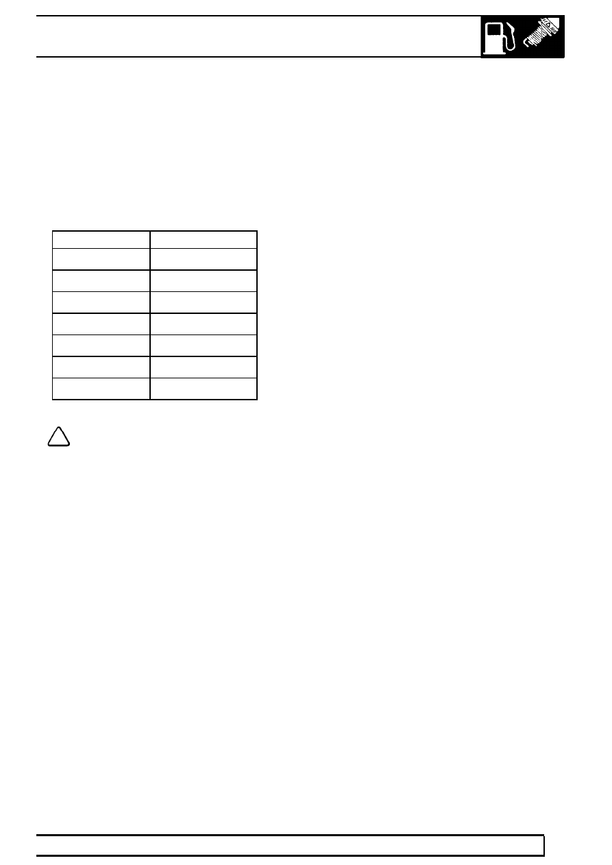
Temperature

Voltage

-50

°

C

5V

-20

°

C

4.8V

10

°

C

4.2V

40

°

C

2.8V

70

°

C

1.4V

100

°

C

0.6V

130

°

C

0.2V

NOTE: All voltages listed are approximate.

A coolant temperature circuit failure may result in the
following symptoms:

Poor cold and warm/hot starting and driveability.

Instrument pack temperature warning lamp will
illuminate.

MIL will be illuminated.

Temperature gauge reads excessively hot or
cold.

Cooling fan will not run

SAI pump will operate at engine start up even
when engine is hot (NAS with secondary air
injection system only).

The ECT sensor can fail in the following ways, or
supply an incorrect signal:

Sensor open circuit.

Short circuit to vehicle supply.

Short circuit to earth.

Incorrect mechanical fitting.

Signal fixed above 40

°

C (140

°

F) will not be

detected.

Signal fixed below 40

°

C (140

°

F) not detected.

Should a malfunction of the component occur, the
following fault codes may be evident and can be
retrieved by Testbook:

P0116 - (Signal differs too much from
temperature model for longer than 2.54s)

P0117 - (Open circuit or short circuit to battery
supply)

P0118 - (Short circuit to ground)

19

FUEL SYSTEM

NEW RANGE ROVER

48

DESCRIPTION AND OPERATION

Knock Sensors (KS) - from 99MY

The ECM utilises active knock control, which serves to
prevent engine damage through pre-ignition or
detonation. Knock control is effective under all
operating conditions, enabling the engine to operate
without additional safety margins.

Two knock sensors are used, one mounted each side
of the cylinder block between the two centre cylinders
of each bank. Each sensor has two wires; a signal
wire providing input to the ECM and a ground
(screen). Each of the sensors monitor the ’knock’ from
four cylinders (Cylinder No’s: 1, 3, 5 & 7 and Cylinder
No’s: 2, 4, 6 & 8).

CAUTION: The connector and sensor
terminals are gold plated to provide good
conductivity and resistance to corrosion

and high temperatures. Be careful not to damage
terminals if probing with test equipment.

The knock sensors consist of piezo-ceramic crystals
that oscillate to create a voltage signal. During
pre-ignition, the frequency of crystal oscillation
increases which alters the signal output to the ECM.

The signal is processed by comparing it to signal
profiles contained in memory which indicate a
pre-ignition condition. If pre-ignition conditions are
evident, the ECM retards the ignition on that cylinder
for a number of cycles. The ignition timing gradually
reverts to its original setting.

The ignition system is calibrated to run on 95 RON
Premium fuel for optimum fuel economy and
performance characteristics. The system can also
function satisfactorily with 91 RON Regular fuel. If the
vehicle is refuelled with a lower grade of fuel some
audible detonation may be heard until the system
adaptions are complete for the new fuel grade.

If a knock sensor should fail, the following symptoms
may be observed:

Possible rough running

Reduction in engine performance

A knock sensor failure is likely to occur for the
following reasons:

Sensor open circuit

Short circuit to vehicle supply or ground

Faulty component

Loose sensor - incorrectly torqued

If knock control is disabled, a default "safe ignition
map" is used.

If a knock sensor should fail, the following fault codes
will be generated by the ECM diagnostics, which can
be retrieved by Testbook:

P0327 - (LH bank signal less than the threshold
value determined from the ECM model above
2200 rpm)

P0328 - (LH bank signal greater than the
threshold value determined from the ECM model
above 2200 rpm)

P0332 - (RH bank signal less than the threshold
value determined from the ECM model above
2200 rpm)

P0333 - (RH bank signal greater than the
threshold value determined from the ECM model
above 2200 rpm)

Noise induced on the battery supply line could be
misinterpreted as a knock signal and cause a
maximum knock fault. A maximum fault could be
caused by a short circuit to the battery supply or in the
case of extreme mechanical engine noise / piston
slap. A minimum fault is usually due to an open circuit.

LAND ROVER V8

49

DESCRIPTION AND OPERATION

Ignition coils

The electronic ignition system is fitted with two quad
coils which are directly driven by the ECM. The
ignition coils are mounted on a bracket fitted to the
rear of the engine. The circuit to each coil is
completed by switching within the ECM, allowing each
coil to charge. When the ECM determines the correct
ignition point, it switches off current supply to the coil
which in turn causes the magnetic field around the
coil’s primary winding to collapse, inducing ht voltage
in the secondary winding and in the iron core of the
coil. High tension voltage, of different polarities, is
produced at either end of the coil’s core and is
transmitted to two cylinders simultaneously, one on
compression stroke, the other on exhaust stroke. This
is called the wasted spark principle.

Note that coil 1 feeds cylinders 1 and 6, coil 2 feeds
cylinders 5 and 8, coil 3 feeds cylinders 4 and 7, and
coil 4 feeds cylinders 2 and 3. The resistance of the
spark plug in the compression cylinder is higher than
that in the exhaust cylinder and hence more spark
energy is dissipated in the compression cylinder. Coil
failure will result in a lack of ignition, resulting in a
misfire in the related cylinders. The fault is indicated
by illumination of the malfunction indicator light (MIL)
on North American specification vehicles.

The positive supply to the coils is fed via a common
fuse and ignition relay located in the engine
compartment fusebox. Each coil supply feed has an
RFI suppression capacitor fitted adjacent to the coil
mounting bracket. The ignition primary wires are
screened to suppress the emission of radio frequency
interference, with the screens being grounded at a
connection on the ECM.

WARNING: The ignition coils operate at
very high voltages, do not attempt repair
operations and procedures on the ignition

high tension / secondary system when the engine
is running.

The ECM calculates the dwell timing from battery
voltage and engine speed data to ensure sufficient
secondary (spark) energy is always available without
excessive primary current flow, thus avoiding
overheating or damage to the ignition coils.

The spark timing for each individual cylinder is
calculated by the ECM using an internal memory map
under consideration of the following inputs:

Engine speed

Engine load

Engine temperature

Knock control

Automatic gearbox shift control

Idle speed control

The nominal value for a warm engine at idle is
12

°

BTDC

CAUTION: Avoid running the engine if
there is a possibility of the secondary (ht)
becoming open circuit. This condition

could damage the ignition power stages and / or
the ignition coils through excessive energy being
reflected back into the primary circuit.

NOTE: Testbook is not able to perform
diagnostics to the primary power stage
coils. Ignition related faults are monitored

indirectly via the misfire detection system and its
fault codes (NAS vehicles only).

19

FUEL SYSTEM

NEW RANGE ROVER

50

DESCRIPTION AND OPERATION

Resistance measurements of the primary and
secondary sides of the ignition coils can be performed
using a suitable multimeter. Default values are:

Nominal primary coil resistance (up to 99MY) =
0.8 ohms

Nominal primary coil resistance (from 99MY) =
0.5 ohms

±

0.05 ohms at 20

°

C (68

°

F)

Nominal secondary coil resistance = 13.3
k-ohms

±

1.3 k-ohms at 20

°

C (68

°

F)

If an ignition coil should fail, the following symptoms
may be observed:

Engine will not start - loss of spark

Engine misfire on specific cylinders

An ignition coil failure is likely to occur for the following
reasons:

Connector or harness fault

Coil open circuit

Short circuit to vehicle battery supply or ground

Faulty component

Fuel injectors - from 99MY

The fuel injectors are located beneath the air inlet
manifold. They utilise an electrical solenoid which lifts
an injector needle off its seat to allow fuel injection to
take place. The fuel injectors provide excellent fuel
atomisation in the lower portion of the inlet manifold,
the air:fuel mixture is then drawn into the cylinders to
provide optimum combustion characteristics and
excellent driveability.

A fuel pressure test point is provided by means of a
Schrader valve positioned between the rear of the
engine and the bulkhead, above the coil packs.

There are eight fuel injectors, one per cylinder which
the ECM operates sequentially. All the injectors are
fed from a common fuel rail as part of the returnless
fuel system. Fuel pressure is maintained at a constant
3.5 bar (52 lbf.in

2

) by a regulator that is integral with

the fuel pump.

CAUTION: The injectors are extremely
sensitive, they must not be dropped or
contaminated.

CAUTION: When assembling the injector
to the fuel rail, only use clean engine oil to
aid assembly. DO NOT use petroleum jelly

or other forms of grease, as this will contaminate
the injector.

The injectors can be checked using a multimeter to
test the resistance values:

Injector resistance at 20

°

C = 14.5 ohms

±

0.7

ohms


Content   ..  93  94  95  96   ..