Range Rover. Manual - part 82


  Index      Land Rover     Range Rover P38 - service manual 1995 year


Search            


Content   ..  80  81  82  83   ..


Range Rover. Manual - part 82


BMW DIESEL

17

REPAIR

FUEL TANK, PUMP AND GAUGE SENDER UNIT

Service repair no - 19.55.01 - Fuel Tank
Service repair no - 19.45.08 - Fuel Pump
Service repair no - 88.25.32 - Fuel gauge Tank Unit

Remove

1. Disconnect battery negative lead.
2. Petrol Models Only: Depressurise fuel system.

See this section.

3. Remove contents of fuel tank into an approved

closed container.

4. Remove fuel filler neck.

See this section.

5. Raise vehicle on four post lift.
6. Position container beneath fuel filter to catch

spillage.

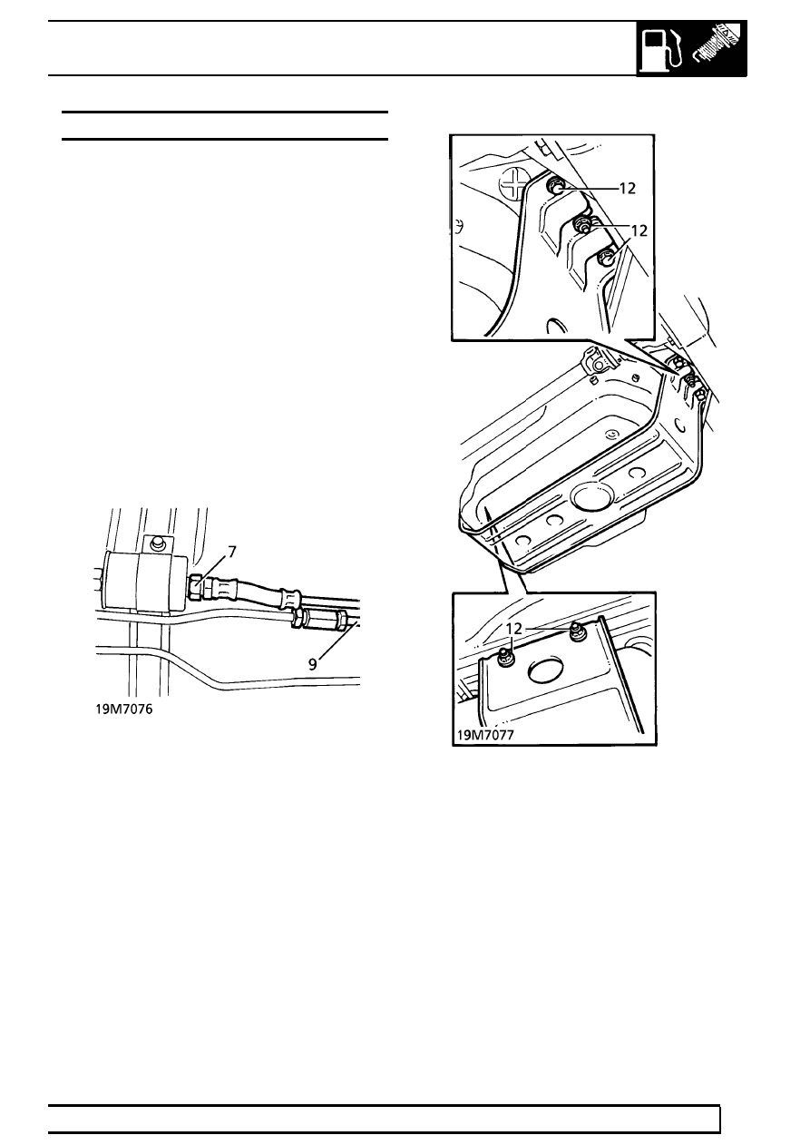
7. Petrol Models Only: Disconnect feed pipe from

fuel filter.

8. Diesel Models Only: Disconnect feed pipe at

connection, forward of fuel tank.

9. Disconnect return pipe, forward of tank.

10. Plug pipes and connections.
11. Support tank with jack.
12. Remove 3 nuts and 2 bolts securing tank cradle

to floor pan.

13. Lower tank by 150mm. Disconnect multiplug

from fuel tank unit.

19

FUEL SYSTEM

NEW RANGE ROVER

18

REPAIR

14. Lower tank assembly. Remove from jack.

Do not carry out further dismantling if
component is removed for access only.

Disassemble

15. Remove tank from cradle.
16. Slacken clip. Remove fill breather pipe from tank

unit.

17. Disconnect feed and return pipes from tank unit.

Remove each pipe from 2 fuel tank clips.

18. Remove tank unit retaining ring using

LRT-19-001. Remove assembly from tank.

WARNING: A quantity of fuel will be
retained in the unit, care must be taken to
avoid excessive spillage during removal.

19. Remove tank unit sealing rubber and discard.

Reassemble

20. Fit new sealing rubber.
21. Fit tank unit. Align location marks.
22. Fit retaining ring using LRT-19-001.
23. Connect fuel feed and return pipes to tank unit.

Tighten to

16 Nm (12 lbf.ft)

24. Secure pipes to fuel tank clips.
25. Position fill breather pipe to tank unit. Secure

with clip.

26. Position tank in cradle.

BMW DIESEL

19

REPAIR

Refit

27. Raise fuel tank assembly on jack until multiplug

can be connected to tank unit.

28. Raise tank. Align cradle mounting points. Secure

with nuts and bolts.

29. Remove plugs from pipes and connections.
30. Petrol Models Only: Using new ’O’ ring,

connect fuel spill return pipe. Tighten to

16 Nm

(12 lbf.ft)

31. Petrol Models Only: Using new ’O’ ring,

connect fuel feed pipe to filter. Tighten to

20 Nm

(15 lbf.ft)

32. Diesel Models Only: Connect fuel feed and

return pipes.

33. Lower vehicle.
34. Refit fuel filler neck.

See this section.

35. Refill fuel tank.
36. Reconnect battery negative lead.

MASS AIR FLOW (MAF) SENSOR - DIESEL WITH
EGR

Service repair no - 19.22.25

Remove

1. Disconnect multiplug from MAF sensor.
2. Slacken clip and disconnect intake hose from

MAF sensor.

3. Remove 2 bolts securing MAF sensor to air

cleaner.

4. Remove MAF sensor and collect ’O’ ring seal.

NOTE: Discard ’O’ ring seal.

Refit

5. Position new ’O’ ring seal to MAF sensor.
6. Engage MAF sensor to air cleaner and secure

with bolts. Tighten bolts to

10Nm (7 lbf.in).

7. Connect intake hose and secure with clip.
8. Connect multiplug to MAF sensor.

19

FUEL SYSTEM

NEW RANGE ROVER

20

REPAIR

DUCTING - AIR INTAKE - DIESEL WITH EGR

Service repair no - 19.10.27

Remove

1. Disconnect battery negative terminal.
2. Remove 4 bolts securing injector cover and

remove cover.

3. Slacken clip securing intake hose to intake

ducting and disconnect hose.

4. Release clip securing breather hose to intake

ducting.

5. Slacken clip securing intake duct to turbo duct.
6. Carefully release intake duct from clips on intake

manifold and camshaft cover.

CAUTION: Care must be taken to ensure
clips do not become damaged.

7. Disengage duct from breather hose and turbo

duct. Remove intake duct assembly.

Refit

8. Position intake duct. Engage turbo duct and

breather hose.

9. Carefully engage intake duct clips to camshaft

cover and inlet manifold locations.

CAUTION: Ensure that manifold clips are
correctly engaged before pushing duct
downwards or clips may be damaged.

10. Connect intake hose to intake duct.
11. Secure clips on intake turbo duct, intake hose

and breather hose.

12. Position injector cover and secure with bolts.

Tighten bolts to Tighten to

10 Nm (7 lbf.in).

13. Connect battery negative terminal.


Content   ..  80  81  82  83   ..