Range Rover. Manual - part 67
 

  Index      Land Rover     Range Rover P38 - service manual 1995 year


Search            


Content   ..  65  66  67  68   ..


Range Rover. Manual - part 67


EMISSION CONTROL

29

DESCRIPTION AND OPERATION

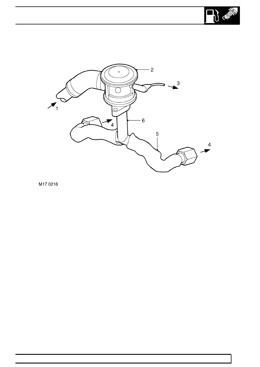
SAI control valves

1. Pressurised air from SAI pump
2. Vacuum operated SAI control valve
3. Vacuum hose from SAI vacuum solenoid valve
4. Pressurised air to exhaust manifold
5. Protective heat sleeving
6. Air delivery pipe to exhaust manifold

The SAI control valves are located on brackets at
each side of the engine.

The air injection supply pipes connect to a large bore
port on the side of each SAI control valve via a short
rubber connection hose. A small bore vacuum port is
located on each SAI control valve at the opposite side
to the air injection supply port. The vacuum supply to
each vacuum operated SAI control valve is through
small bore nylon hoses from the SAI vacuum solenoid
valve. An intermediate connector is included in the
vacuum supply line to split the vacuum applied to
each SAI control valve, so that both valves open and
close simultaneously.

When a vacuum is applied to the SAI control valves,
the valve opens to allow the pressurised air from the
SAI pump through to the exhaust manifolds. The
injection air is output from each SAI control valve
through a port in the bottom of each unit. A metal pipe
connects between the output port of each SAI control
valve and each exhaust manifold via an intermediate
T-piece. The T-piece splits the pressurised air
delivered to ports at the outer side of the two centre
exhaust ports on each cylinder head. The pipes
between the T-piece and the exhaust manifold are
enclosed in thermal sleeving to protect the
surrounding components from the very high heat of
the exhaust gas, particularly at high engine speeds
and loads.

When the SAI vacuum solenoid valve is de-energised,
the vacuum supply line opens to atmosphere, this
causes the vacuum operated valves to close
automatically and completely to prevent further air
injection.

17

EMISSION CONTROL

NEW RANGE ROVER

30

DESCRIPTION AND OPERATION

Vacuum reservoir

1. Vacuum port to SAI vacuum solenoid valve
2. Vacuum port to intake manifold (one-way valve end)
3. Vacuum reservoir

A vacuum reservoir is included in the vacuum supply
line between the intake manifold and the SAI vacuum
solenoid valve. The vacuum reservoir contains a
one-way valve, to stop depression leaking back
towards the intake manifold side. The reservoir holds
a constant vacuum so that the SAI control valves
open instantaneously as soon as the SAI vacuum
solenoid valve is energised.

The vacuum reservoir is a plastic canister construction
located on the SAI pump bracket at the RH side of the
engine compartment. It is important to ensure the
reservoir is fitted in the correct orientation, and the
correct vacuum hoses are attached to their
corresponding ports. The one-way valve end of the
reservoir is the cap end which connects to the inlet
manifold.

A small bore nylon hose is used to connect the
one-way valve end of the vacuum reservoir to a port
on the RH side of the inlet manifold. A further small
bore nylon hose connects between the other port on
the vacuum reservoir and a port on the front of the
SAI vacuum solenoid valve.

EMISSION CONTROL

31

DESCRIPTION AND OPERATION

EVAPORATIVE EMISSION SYSTEM CONTROL
COMPONENTS - (from 99MY)

Purge valve

1. Direction of flow indicator
2. Inlet port - from EVAP canister
3. Outlet port - to inlet manifold
4. Harness connector

The EVAP canister purge valve is located in the
engine bay at the LH side of the engine intake
manifold. On NAS vehicles with secondary air
injection, the purge valve is fixed to a metal bracket
together with the SAI vacuum solenoid valve; the
purge valve is fixed to the bracket by two plastic clips.

The outlet side of the purge valve is connected to a
stub pipe on the back of the inlet manifold plenum
chamber (through a combination of rubber and nylon
pipes). The connector to the plenum chamber stub
pipe is a quick-release type, plastic 90

°

female elbow.

A short hose/pipe is connected between the inlet side
of the purge valve and a service port.

The purge valve has a plastic housing, and a
directional arrow is moulded onto the side of the
casing to indicate the direction of flow. The head of
the arrow points to the outlet side of the valve which
connects to the plenum chamber.

A service port is connected in line between the EVAP
canister and the inlet side of the purge valve and is
rated at 1 psi maximum regulated pressure. The
service port must be mounted horizontally and is
located close to the bulkhead at the rear left hand side
of the engine bay.

The service port is used for pressure testing using
specialist nitrogen test equipment for localising the
source of leaks. A pipe/hose from the inlet side of the
service port connects to a quick-fit connector that
mates to the purge pipe leading to the EVAP canister
beneath the vehicle.

Purge valve operation is controlled by the engine
control module (ECM). The purge valve has a two-pin
electrical connector which links to the ECM via the
engine harness. Note that the harness connector to
the SAI solenoid valve is grey, and must not be
confused with the harness connector to the EVAP
system purge valve which is black.

One pin of the connector is the power supply source
and the other is the switched earth from the ECM
(pulse width modulated (PWM) signal) which is used
to control the purge valve operation time.

When the purge valve is earthed by the ECM, the
valve opens to allow hydrocarbons stored in the EVAP
canister to be purged to the engine inlet manifold for
combustion.

If the purge valve breaks or becomes stuck in the
open or closed position, the EVAP system will cease
to function and there are no default measures
available. The ECM will store the fault in memory and
illuminate the MIL warning lamp. If the purge valve is
stuck in the open position, a rich air:fuel mixture is
likely to result at the intake manifold, this could cause
the engine to misfire and fuelling adaptions will
change. The following failure modes are possible:

Sticking valve

Valve blocked

Connector or harness wiring fault (open or short
circuit)

Valve stuck open

17

EMISSION CONTROL

NEW RANGE ROVER

32

DESCRIPTION AND OPERATION

Canister Vent Solenoid (CVS) unit - (NAS only)

1. CVS unit
2. Mounting bracket
3. Spring clips to pipe from EVAP canister
4. Harness connector

The CVS unit is mounted at the rear right hand side of
the engine bay on a slide-on bracket. The vent pipe
from the EVAP canister is connected to a stub pipe on
the CVS unit via a short rubber hose. The rubber hose
is connected to the CVS unit and plastic pipe by two
metal band clips. A two-pin connector links to the
engine management ECM via the engine harness for
solenoid control. One wire is for the voltage feed, the
other is the valve drive line to the ECM. The solenoid
is operated when the ECM grounds the circuit.

The valve is normally open, allowing any build up of
air pressure within the evaporation system to escape,
whilst retaining the environmentally harmful
hydrocarbons in the EVAP canister.

When the ECM is required to run a fuel evaporation
system test, the CVS valve is energised and closes to
seal the system. The ECM is then able to measure the
pressure in the EVAP system using the fuel tank
pressure sensor. The ECM performs electrical
integrity checks on the CVS valve to determine wiring
or power supply faults. The ECM can also detect a
valve blockage if the signal from the fuel tank
pressure sensor indicates a depressurising fuel tank
while the CVS valve should be open to atmosphere.
The following failure modes are possible:

Connector or wiring harness fault (open or short
circuit)

Valve stuck open or shut

Valve blocked


Content   ..  65  66  67  68   ..