Frelander 2. Manual - part 679
30.
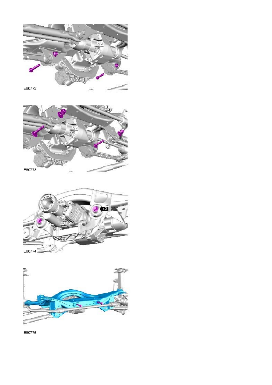
31.
Discard the bolts.
32.
Discard the bolts.
33.
With assistance, remove the rear subframe.
34.
Installation
|
|
|
30. 31. Discard the bolts. 32. Discard the bolts. 33. With assistance, remove the rear subframe. 34. Installation |