Frelander 2. Manual - part 677
1.
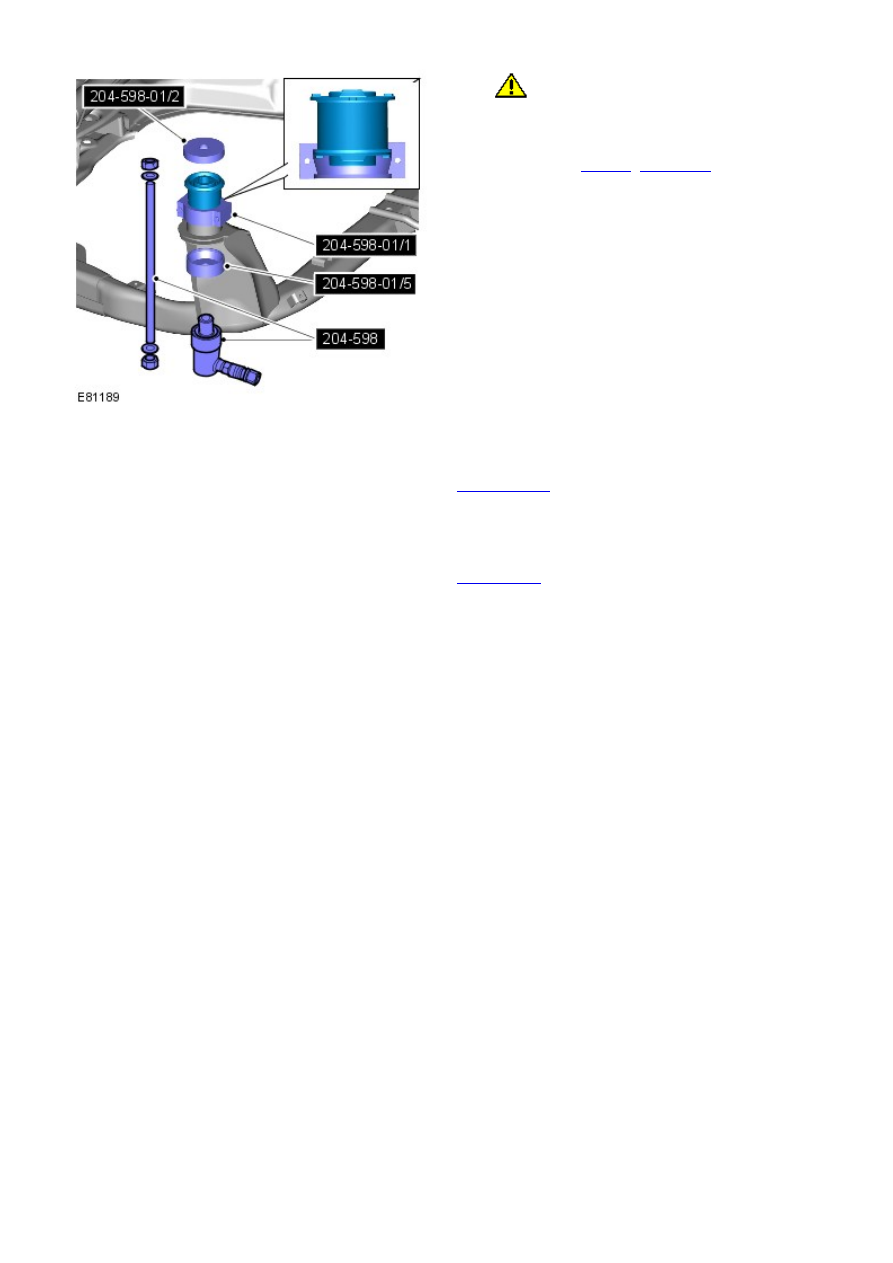
CAUTION: Make sure that the component aligns
with the installation mark.
Install the bushing.
Special Tool(s):
204-598
,
204-598-01
1.
Install the front subframe.
Refer to:
Front Subframe
(502-00 Uni-Body, Subframe and Mounting
System, Removal and Installation).
2.
Connect the battery ground cable and install the cover.
Refer to:
Specifications
(414-00 Battery and Charging System -
General Information, Specifications).
3.