Frelander 2. Manual - part 583


  Index      Land Rover     Land Rover Frelander 2 - service repair manual 2006-2010 year


Search            


Content   ..  581  582  583  584   ..


Frelander 2. Manual - part 583


Handles, Locks, Latches and Entry Systems - Liftgate Striker Adjustment

General Procedures

Check for an equal gap and alignment to the adjacent
panels. If incorrect, follow the adjust procedure below.
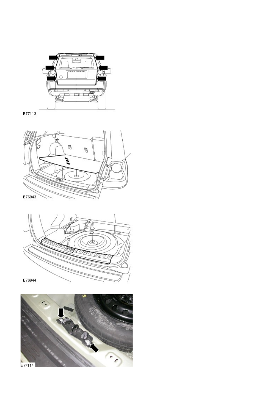
1.

Remove the spare wheel cover.

2.

Remove the loadspace scuff plate.

3.

Loosen the 2 liftgate striker bolts.

4.

Close the liftgate and check for an equal gap and alignment to the
adjacent panels.

5.

Open the liftgate and tighten the liftgate striker bolts.

Torque: 25 Nm

6.

Install the loadspace scuff plate.

7.

Install the spare wheel cover.

8.

Handles, Locks, Latches and Entry Systems - Front Door Latch

Removal and Installation

Removal

Disconnect the battery ground cable.

Refer to: 

Specifications

 (414-00 Battery and Charging System -

General Information, Specifications).

1.

Remove the window motor and regulator assembly.

Refer to: 

Front Door W indow Regulator and Motor

 (501-11 Glass,

Frames and Mechanisms, Removal and Installation).

2.

3. 

CAUTION: Release the exterior door handle and screw cover

clips from inside the door.

Remove the front door exterior handle.

Refer to: 

Exterior Front Door Handle

 (501-14 Handles, Locks, Latches

and Entry Systems, Removal and Installation).

3.

Release the remote control cable.

4.

Release the door exterior handle mechanism.

5.

Remove the front door latch assembly.

6.

7. NOTE: Do not disassemble further if the component
is removed for access only.

Remove the door latch remote control cable.

7.

Release the exterior door handle mechanism cable from
the door latch.

8.

LH side: Release the door lock cylinder cable from the
door latch.

9.

Installation

LH side: Connect the door lock cylinder cable to the door latch.

1.

Connect the door exterior handle mechanism cable to the door latch.

2.

Install the remote control cable to the door latch.

3.


Content   ..  581  582  583  584   ..