Frelander 2. Manual - part 515


  Index      Land Rover     Land Rover Frelander 2 - service repair manual 2006-2010 year


Search            


Content   ..  513  514  515  516   ..


Frelander 2. Manual - part 515


Anti-Theft - Passive - Anti-Theft - Passive

Description and Operation
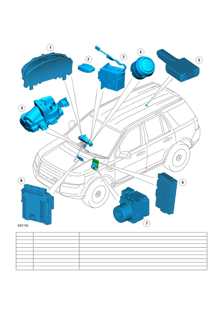
COMPONENT LOCATION

Item

Part Number

Description

1

-

Instrument cluster

2

-

Remote handset

3

-

Start control module

4

-

Stop/Start switch

5

-

Radio Frequency (RF) receiver

6

-

Central Junction Box (CJB)

7

-

Anti-lock Brake System (ABS) module

8

-

Engine Control Module (ECM)

9

-

Electric steering column lock

OVERVIEW

The Passive Anti-Theft System (PATS - immobilization) provides a secure interface between the CJB , ECM and ABS module
to prevent unauthorized starting of the vehicle. This is achieved by having uniquely coded remote handset and encoded
data exchange between modules.

Unauthorized starting prevention is achieved by immobilization of the engine crank system, fuel system and ignition
system.

The passive anti-theft system uses the following components:

Remote handset transponder
CJB
ECM
Start control module
Instrument cluster
ABS module
Electric steering column lock (if enabled).

• NOTE: On North American Specification (NAS) vehicles, a running change was introduced during 2008 Model Year (MY) to
disable the electric steering column lock. Under the change, the internal electronics (printed circuit board (PCB), motor,
etc.) of the lock have been removed and the lock has been disabled in the car configuration file. The change is
incorporated on 

VIN (vehicle identification number)

 082896, 085531, 085622, 085685, 085832, 085891, 085942, 085987,

086049, 086081, 086123, 086178, 086276, 086287, 086309, 086363, 086383, 086389, 086398, 086403 and 091770
onwards.

The system is automatic and requires no input from the driver. The engine management system will only allow engine
crank when an authorization data message is received from the CJB. The engine start system is initiated when the
start/stop switch and the brake pedal (automatic transmission) or the clutch pedal (manual transmission) are pressed
simultaneously.

The engine management system (ECM) will only allow engine crank, spark (petrol models only) and injector functions when
the following conditions are met:

A hardwired Park/Neutral signal is received from the Transmission Control Module (TCM) (automatic transmission
only)
A hardwired ignition signal is received from the CJB
A hardwired crank request signal is received from the CJB
Encrypted data exchange between the instrument cluster and the ECM is verified.

Before the CJB will send the hardwired ignition signal, it must satisfactorily complete the following:

Exchanged encrypted data with the start control module to validate the remote handset.

Additionally, before the CJB will send the hardwired crank request signal it must receive the following signals:

Brake signal from the brake switch (automatic transmission) or clutch signal from the clutch switch (manual
transmission)
Hardwired transmission in Park (P) signal from the selector lever assembly (automatic transmission only).

CONTROL DIAGRAM

• NOTE: = Hardwired; = High speed CAN bus; = Medium speed CAN bus; = LIN bus; = LF transmission

Item

Part Number

Description

1

-

Battery

2

-

Battery Junction Box (BJB)

3

-

ABS module

4

-

ECM

5

-

Stop/Start switch

6

-

Start control module

7

-

Remote handset

8

-

Electric steering column lock (if enabled)

9

-

CJB

10

-

Instrument cluster

START CONTROL MODULE

The start control module is located in the instrument panel, adjacent to the steering column. The start control module is
used as a primary method to authorize the remote handset.

The remote handset is inserted into the start control module slot with the key fob loop trailing. The start control module is
motorized and will draw the remote handset into the slot once inserted.

The start control module will then read the transponder within the remote handset and, if the transponder identification is
valid, pass the identification data to the CJB to be processed.

Five seconds after the remote handset is inserted in the start control module, the module will start to charge the remote
handset battery.

A message 'KEY IN' will be displayed if the remote handset is still in the start control module and the driver's door is

opened. The remote handset is removed from the start control module by gently pushing the remote handset into the start
control module and releasing. The start control module motor will then drive the remote handset out from the slot as long
as the ignition is off.

RF RECEIVER

The Radio Frequency (RF) antenna is located in a central position behind the head liner. The receiver is available in two
variants; 315 MHz or 433 MHz depending on market requirements. Transmissions are received from the remote handset for
key identification and remote lock/unlock requests or requests for operation of the additional driver convenience features.

PRINCIPLES OF OPERATION

The remote handset is validated via the start control module and the CJB. If the remote handset is valid the CJB initiates
the unlocking of the electric steering column lock (if enabled). Once the electric steering column lock is unlocked and power
has been removed, then the CJB enables the Fuel Pump Driver Module (FPDM) on petrol vehicles or the fuel pump relay on
diesel vehicles.

The CJB also controls the engine crank request. On vehicles with automatic transmission, if the transmission selector lever
is in the Park 'P' position and the driver presses the brake pedal or on manual transmission vehicles if the driver presses
the clutch pedal and simultaneously presses the start/stop switch, the CJB interprets this as an engine crank request.
Before the engine crank request is allowed, the CJB checks for the brake or clutch switch signal. If the signal is correct
then the CJB sends a crank request signal to the ECM on the high speed Controller Area Network (CAN) bus.

If a replacement remote handset is required, then a Land Rover approved diagnostic system must be used to synchronize
the remote handsets. If any module, which is involved in the remote handset authorization process, require replacement, a
Land Rover approved diagnostic system procedure is also required to synchronize the replacement module into the system.


Content   ..  513  514  515  516   ..