Frelander 2. Manual - part 492
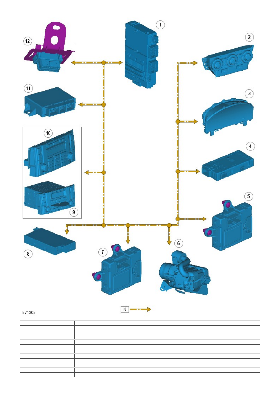
Item
Part Number
Description
1
-
CJB
2
-
ATC module
3
-
Instrument cluster (Intelligent Drivers Module)
4
-
Trailer module
5
-
Driver door module
6
-
Fuel fired booster heater
7
-
Passenger door module
8
-
Seat memory module
9
-
Integrated head unit/Integrated control module - Low line audio
10
-
Integrated control module - High line audio
11
-
Parking aid module