Frelander 2. Manual - part 468


  Index      Land Rover     Land Rover Frelander 2 - service repair manual 2006-2010 year


Search            


Content   ..  466  467  468  469   ..


Frelander 2. Manual - part 468


Clock
Antenna power
Light Emitting Diode (LED) illumination.

In transit mode the CAN port and the ON/OFF switch are the only circuits that are left active.

The CAN port is left open to allow the EXIT from transit mode signal to be received. The ON/OFF switch is left active to
allow feedback to the driver via the head unit LCD (liquid crystal display), that the unit is in transit mode should the driver
attempt to power up the head unit. This will only occur when the vehicle engine is running and the battery is above 12.3
Volts.

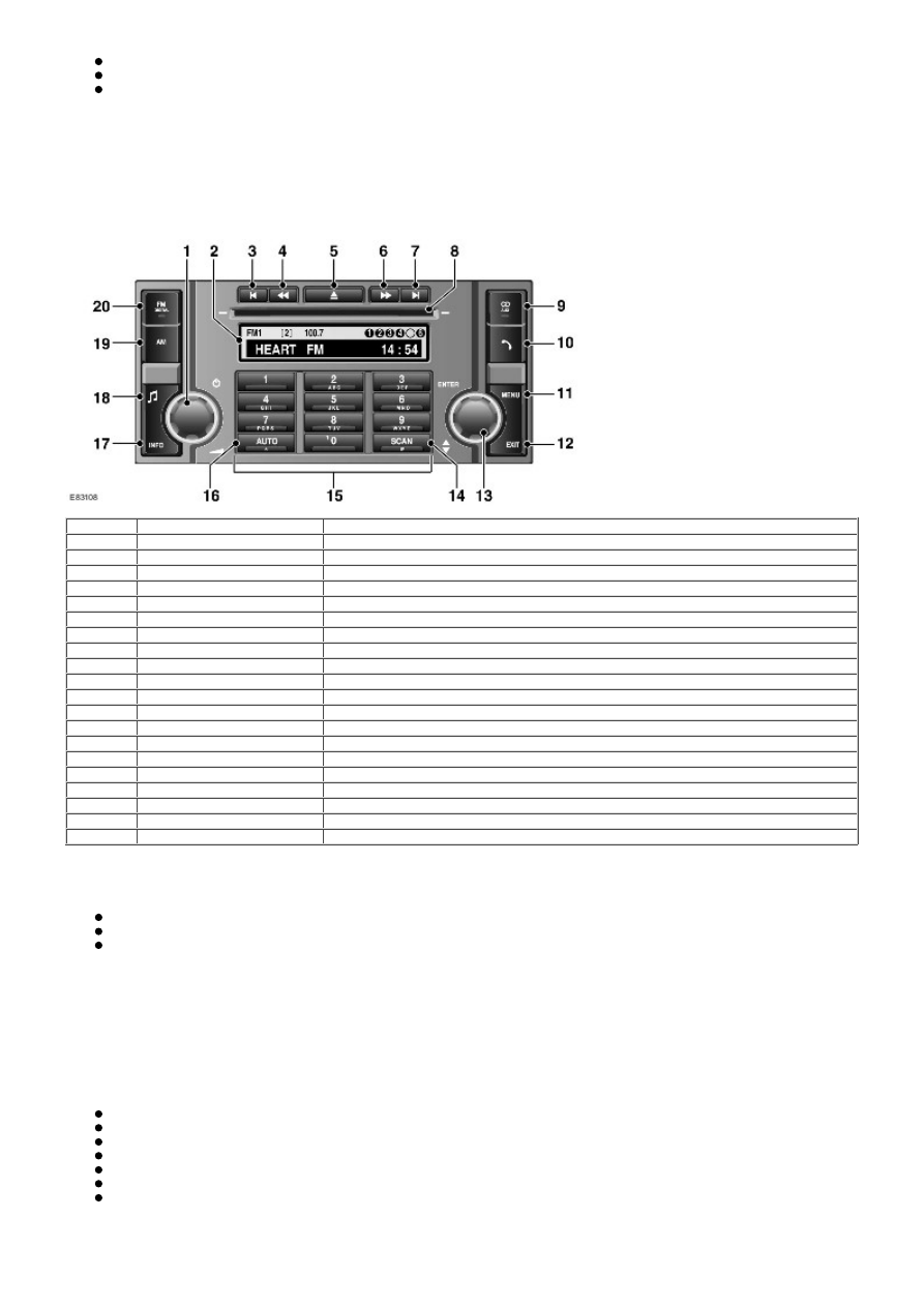
HIGH LINE AUDIO SYSTEM

Item

Part Number

Description

1

-

On/Off volume control

2

-

Information display

3

-

Seek down/previous track

4

-

Manual tuning down/CD previous track

5

-

CD eject

6

-

Manual tuning up/CD next track

7

-

Seek up/next track

8

-

CD slot

9

-

Mode button

10

-

Telephone mode button

11

-

Audio menu button

12

-

Exit button

13

-

Audio menu rotary controller

14

-

Scan button

15

-

Keypad

16

-

Autostore button

17

-

Info button

18

-

Tone/volume settings button

19

-

AM waveband button

20

-

FM waveband button

The High Line Audio system is based around an Integrated Audio Module (IAM) which communicates on the Media
Orientated System Transport (MOST). The ICM communicates on medium speed CAN and MOST buses.

The IAM contains the following functionality:

Radio tuner
CD player (Single CD or Six disc in dash changer)
Auxiliary input (for any device featuring a 3.5mm jack plug output).

The ICM is woken up by CAN bus activity. The IAM is woken up by the MOST ring.

The ICM is the Bus Master for the MOST system and contains the timing master for the MOST system.

TUNER

The IAM incorporates a AM/FM tuner which allows for 30 FM pre-sets (FM1 FM2 FM a) and 20 AM (10 AM and 10 AM a, for
Europe the 10 strongest LW and MW will be stored in frequency order). Pre-set stations are stored in the IAM and ICM
memory. The radio tuner also incorporates the following radio functions:

Auto tune
Traffic announcements (TA) – Europe only
Radio Data System (RDS) EON function (Radio Broadcast Data System RBDS in NAS markets)
Seek station
Tune up/down
Scan
PTY

• NOTE: On vehicles fitted with the HD radio module, the module replaces the AM/FM function in the IAM. AM and FM
antennae are connected directly into the HD radio module and not into the IAM; therefore the AM/FM functions in the IAM

are disabled.

CD PLAYER

The IAM CD player is a 6 disc multi changer located in the center of the instrument panel. The CD multi changer is capable
of playing commercial CDs, CDRs, CDRW s and MP3 discs.

Random Play

The random play feature works in two different ways:

Random play of tracks on a CD
Random play of all tracks on any CD in the autochanger

The single disc random feature plays all the tracks on the selected CD in a random order. All the tracks on that disc will be
played before a new random sequence is played. If a new CD is selected while in random mode, the random mode will be
cancelled and play will commence from the first track.

In multi disc mode the IAM uses the current track as the first random track and will then play a further 2 tracks (if
available) from this CD. The IAM will then randomly select another CD, and play 3 random tracks. This sequence continues
until all tracks from all CD's are played back.

MP3 Function

The CD player has the capability to play MP3 files. The MP3 discs follow a format of folders and files within the folder. It is
also possible to place all the files in the root directory on the CD.

The random and repeat features follow the normal CD random and repeat feature functions.

Automatic Volume Control (AVC)

AVC controls the audio volume in relation to vehicle speed. As vehicle speed increases the audio level is adjusted to
compensate for extra road and vehicle noise. There are 4 settings for AVC:

Off
Low
Medium
High

The default setting is medium.

Changing the AVC level is accessed by a long press of the TONE button and selection of the AVC using the rotary encoder
to change the level.

The vehicle speed signal is used to enable the ICM to calculate the volume adjustment required. The vehicle speed signal
is received over the medium speed CAN. The signal is an average of the four wheel speed sensor signals. Should an invalid
speed signal be received the AVC will not alter the output volume.

AVC is controlled by the audio amplifier.

CD Error Messages

When an CD error occurs, the IAM will alert the user by showing a display related to the error. This will be displayed while
the CD audio mode is selected until the error is corrected. The CD related error does not affect other areas of the IAM. The
user is able to select a different audio source.

Error Message in IAM display

Cause

Deck error

Mechanical Error, CD stuck, Servo related error, etc.

Hot disc

Internal CD temperature too high

Disc unreadable

Invalid Disc, CD ROM inserted, disc inserted upside-down, etc.

AUXILIARY SOCKET

The auxiliary connector is located at the rear of the center console. AUX (Auxiliary Input) mode allows extra equipment to
be connected to the vehicle's audio system. Items such as a personal stereo, MP3 player, hand-held navigation unit etc.,
can be plugged in to the vehicle's audio system.

To listen to an auxiliary input source the portable device must be connected via the 3.5 mm stereo jack socket. If the
device has a line out socket it is preferable that this is used for connection. Press and hold the AUX button on premium
audio units. On standard audio units, press and release the AUX button.

REAR SEAT HEADPHONE MODULES

Item

Part Number

Description

1

-

Headphone socket

2

-

CD select button

3

-

Mode button

4

-

Search up button

5

-

Volume increase button

6

-

Volume decrease button

7

-

Search down button

The rear seat headphone modules are located on the rear of the center console. The rear seat headphone modules allow
the rear seat passenger to listen to audio via standard headphones. The modules allow the rear seat passengers to control
which audio source they want to listen to and the volume. The rear headphone modules do not override the control of the
audio head unit.

STEERING WHEEL CONTROLS

Item

Part Number

Description

1

-

Mode button

2

-

Volume increase button

3

-

Volume decrease button

4

-

Radio seek up/down, Next preset/previous preset, CD next/previous track button

The steering wheel mounted audio control switches are located on the RH side of the steering wheel. The switches are a
resistive ladder type which return a different voltage to the ICM in response to different switches being pressed.
For additional information, refer to: 

Steering Column Switches

 (211-05 Steering Column Switches, Description and

Operation).

SDARS (NAS Only)

The SDARS systems operate in the S-Band frequency range (2.3 GHz) and, as a result of the use of satellite transmission
have the ability to provide CD quality audio broadcasts over very large areas (typically continents). SDARS service
providers transmit a signal from their up-link facility (which is the original point of transmission of data, voice or other
information through an antenna system) to a satellite where the signal is then down linked to both the terrestrial repeater
network and the individual SDARS car radios. The radio switches between the satellite signal and the repeater signal
depending on the strength of the signal at any given time.

Land Rover will be using the Sirius Satellite Radio service provider in the USA.

The SDARS systems comprise:

Satellites
Ground repeaters
Up-link ground stations
Radio receiver systems

The SDARS system uses three satellites on an inclined elliptical orbit. This ensures that each satellite spends
approximately 16 hours a day over the continent of the USA, with at least one satellite over the country at any one time.

The satellites beam their signals down to the ground where the signal is picked up by receivers or is transmitted to
repeater stations to cover built up areas where the signal is obscured.

SDARS is a subscription based service which requires the user to contact Sirius to obtain a subscription. In order to obtain
a subscription the SDARS unit ID number will need to be retrieved from the unit. This is achieved as follows:

Press the MENU button and then rotate the menu control to scroll to advanced settings.
Rotate the menu control to scroll to SIRIUS ID and press the menu control to select it.
The Sirius ID is shown on the display screen.

If no subscription has been taken the ICM will display the Sirius telephone number. To subscribe to Sirius use the
displayed phone this number. The user will need payment details, the Sirius ID number and details of the required
package.

The SDARS function is accessed by pressing the FM button and then pressing again to toggle through the SAT1 and SAT2
sources. SAT1 and SAT2 operate in the same manner as FM1 and FM2.

The SDARS module is located in the rear Left Hand (LH) side of the luggage compartment. The SDARS module is connected
to the rest of the audio system on the MOST ring. This allows control signals and received audio to be routed around the
system to the relevant module. The SDARS antenna is located in the roof mounted pod and is hardwired to the SDARS
module.

HIGH DEFINITION (HD) RADIO - From 2009MY (NAS Only)

HD radio is the registered trademark for the In-Band On-Channel (IBOC) technology selected by the Federal
Communications Commission (FCC) for terrestrial digital audio broadcasting in the United States. A large number of radio
stations now broadcast in both AM and FM. FM frequencies are capable of transmitting multiple frequency streams on a
single FM frequency. HD radio has an advantage over SDARS in that it is free to receive and requires no subscription.

HD radio enhances the sound quality of the received signal so that FM reception gives near CD quality digital reproduction
and AM reception sounds as rich as analog FM stereo. Both AM and FM HD radio offer static-free, crystal-clear reception. An
additional benefit is FM Multicasting – the ability to broadcast multiple program streams over a single FM frequency (for
example 97.7-1, 97.7-2, etc.). The HD radio module is capable of receiving the traditional analogue transmissions of radio
stations not transmitting digital broadcasts in addition to receiving the digital transmissions broadcast alongside the
analogue transmissions from radio stations who offer digital output.

The HD radio module replaces the AM/FM function in the IAM. AM and FM antennae are connected directly into the HD radio
module and not into the IAM; therefore the AM/FM functions in the IAM are disabled.

The broadcast audio signals are digitally compressed by the radio transmitter. Audio is also transmitted in its current


Content   ..  466  467  468  469   ..