Frelander 2. Manual - part 465
Information and Entertainment System - General Information - Information
and Entertainment System
Diagnosis and Testing
Principles of Operation
For a detailed description of the Information and Entertainment systems, refer to the relevant Description and Operation
section in the workshop manual. REFER to:
Audio System
(415-01 Information and Entertainment System, Description and Operation),
Speakers
(415-01 Information and Entertainment System, Description and Operation),
Navigation System
(415-01 Information and Entertainment System, Description and Operation),
Antenna
(415-02 Antenna, Description and Operation).
Inspection and Verification
CAUTION: Diagnosis by substitution from a donor vehicle is NOT acceptable. Substitution of control modules does
not guarantee confirmation of a fault, and may also cause additional faults in the vehicle being tested and/or the donor
vehicle.
1. Verify the customer concern.
1.
2. Visually inspect for obvious signs of mechanical or electrical damage and system integrity.
2.
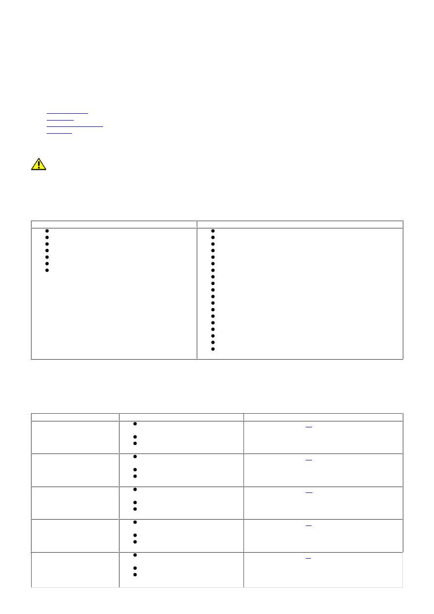
Visual Inspection
Mechanical
Electrical
Integrated audio module
Information and entertainment module
Audio amplifier
Compact disc player jammed, not loading
Scratched/dirty compact discs
Speakers
Navigation system DVD player mechanism
Fuses
Wiring harness
Correct engagement of electrical connectors
Loose or corroded connector(s)
Routing of fibre optic harnesses
Correct engagement of optical connectors
Correct placement of optical connectors (ring order)
Correct assembly of optical connectors (backout, etc)
Damage to fibre (chafing, abrasion, kinking, cuts, etc)
Integrated audio module
Information and entertainment module
Audio amplifier
Speakers
Navigation system display
Navigation system module
GPS antenna
Wiring harness for damage and corrosion
ABS Module
Audio unit
3. If an obvious cause for an observed or reported concern is found, correct the cause (if possible) before
proceeding to the next step.
3.
4. If the cause is not visually evident, check for Diagnostic Trouble Codes (DTCs) and refer to relevant DTC Index.
4.
Navigation System Symptom Chart
Symptom
Possible Cause
Action
Poor satellite reception
Electrical harness open/short
circuit, dis-connected
Component failure
No reception from satellite
GO to Pinpoint Test
B.
Map disc will not insert/eject
Electrical harness open/short
circuit, dis-connected
Component failure
Map disc failure
GO to Pinpoint Test
C.
Black screen (navigation
map screen does not
display)
Electrical harness open/short
circuit, dis-connected
Component failure
GVIF cable
GO to Pinpoint Test
D.
Navigation map screen color
is abnormal
Electrical harness open/short
circuit, dis-connected
Component failure
GVIF cable
GO to Pinpoint Test
E.
Vehicle’s current position
mark turns independently
Electrical harness open/short
circuit, dis-connected
Component failure
Vehicle on a turntable in a
parking building
GO to Pinpoint Test
F.
DTC Index
• NOTE: If the control module or a component is suspect and the vehicle remains under manufacturer warranty, refer to the
Warranty Policy and Procedures manual (section B1.2), or determine if any prior approval programme is in operation, prior