Frelander 2. Manual - part 444


  Index      Land Rover     Land Rover Frelander 2 - service repair manual 2006-2010 year


Search            


Content   ..  442  443  444  445   ..


Frelander 2. Manual - part 444


For additional information, refer to: Electronic Engine Controls - 2.2L Diesel (303-14 Electronic Engine Controls - 2.2L
Diesel, Description and Operation).

Overspeed Warning Indicator

The amber overspeed warning indicator is illuminated on receipt of a medium speed CAN bus signal from the CJB when the
vehicle is in power mode 6. The vehicle speed signal originates in the ABS module and is the same as that used by the
speedometer (see above).

The instrument cluster will flash the overspeed warning indicator at a rate of 2 Hz for 5 seconds if a speed of greater than
75 mph (120 kph) is reached. The first flash of the indicator will be accompanied by a chime from the instrument cluster. If
the vehicle stays at this speed, the indicator will remain illuminated after the 5 second flashing period. The instrument
cluster will extinguish the indicator if vehicle speed drops below 71 mph (114 kph).

Stop/Start Vehicles - From 2010 MY

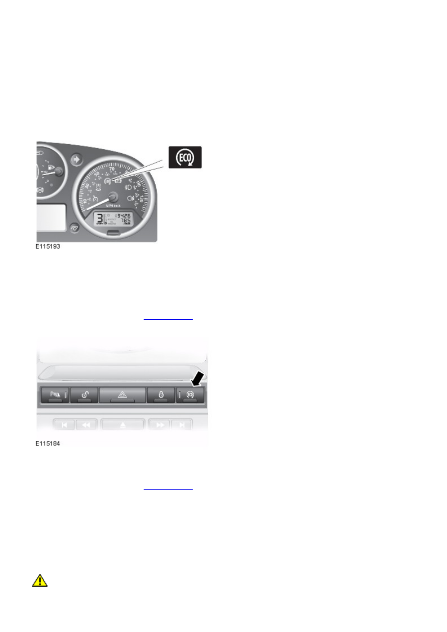
Eco 'Stop/Start' Indicator

The TD4_e introduces the first intelligent ‘Stop/Start’ system into a Land Rover vehicle. The system automatically shuts
down and restarts the vehicle’s engine when the appropriate conditions are satisfied. This reduces the amount of time the
engine spends idling, thereby improving fuel economy and reducing emissions. The driver will be notified that the engine is
shutdown by the ‘Eco’ icon being illuminated in the instrument cluster. Other warning lights normally associated with an
engine shutdown, for example the ignition and low oil pressure indicators are suppressed so will not illuminate during an
engine shutdown in a Stop/Start cycle.
For additional information, refer to: 

Starting System

 (303-06C Starting System - TD4 2.2L Diesel, Vehicles Built From:

01-03-2009, Description and Operation).

Eco Switch

The Stop/Start system is automatically activated each time an ignition cycle occurs. However, the driver can deactivate the
system by pressing the ‘Eco’ switch in the fascia.
For additional information, refer to: 

Starting System

 (303-06C Starting System - TD4 2.2L Diesel, Vehicles Built From:

01-03-2009, Description and Operation).

The Eco switch also operates the Gear Shift Indicator; for additional information refer to Gear Shift Indicator section,
below.

CAR CONFIGURATION FILE

The car configuration file contains all relevant data about the specification and market condition of the vehicle,
immobilization codes and driver personal settings. The master repository for this information is the CJB, with a back up
being held in the instrument cluster. The information is continuously transferred between the 2 components to ensure the
data is constantly backed-up.

CAUTION: W hen a new instrument cluster is to be installed, the Land Rover approved diagnostic system must be

connected to the vehicle and the instrument cluster renewal procedure followed. This will ensure that vehicle coding data
is correctly installed in the new instrument cluster. The Land Rover approved diagnostic system will also record the current

service interval data and restore the settings in the new instrument cluster.

When a new instrument cluster is installed, the Land Rover approved diagnostic system is used to transfer the car
configuration file data from the CJB to the replacement instrument cluster. Vehicle coding data such as engine type and
market is retrieved and used to update the replacement instrument cluster.

The car configuration file will also need to be updated using the Land Rover approved diagnostic system if the vehicle is
modified in service from its original factory specification. This can include fitting non-standard wheels and/or tires, or
optional accessory dealer fit components with an electrical interface.

GEAR SHIFT INDICATOR - FROM 2010 MY

OVERVIEW

A Gear Shift Indicator in the instrument cluster illuminates to advise the driver when to select a higher gear to attain
better fuel efficiency from the vehicle. If the indicator is obeyed the driver can achieve fuel savings of up to 5%.

Gear shift indicator

Introduced in the manual transmission vehicle as standard, the Gear Shift Indicator is automatically activated each time
an ignition cycle occurs. However, the driver can deactivate the indicator by pressing the ‘Eco’ switch on the fascia.

• NOTE: The ‘Eco’ switch also operates the Stop/Start system.

For additional information, refer to: 

Starting System

 (303-06C Starting System - TD4 2.2L Diesel, Vehicles Built From:

01-03-2009, Description and Operation).

Eco switch

The Gear Shift Indicator illuminates to advise the driver to select a higher gear, the indicator depending on driver action
and driving conditions behaves as follows:

Extinguishes when a higher gear is selected.
Extinguishes before a higher gear is selected if driver demand or driving conditions change.
Extinguishes after 12 seconds if the indicator is ignored; either of the two following conditions can reset the
indicator:

- the driver makes a further gear selection,
- the driver accelerates after exiting a sharp corner.

The Gear Shift Indicator is designed only to assist the driver, gear selection remains the driver’s decision based on other
driving conditions affecting the vehicle.

The Gear Shift Indicator:

Does not advise when to select a lower gear.
Cannot predict the gradient or curvature of the road ahead.

CONTROL DIAGRAM

Gear Shift Indicator Control Diagram

• NOTE: A = Hardwired; = High Speed CAN bus; = Medium Speed CAN bus.

Item

Part Number

Description

1

-

Linear clutch sensor

2

-

Steering wheel module including steering angle sensor

3

-

Engine control module

4

-

Mass air flow sensor / Intake air temperature sensor

5

-

Accelerator pedal position sensor

6

-

Coolant temperature sensor

7

-

Crankshaft position sensor

8

-

Instrument cluster

9

-

Eco switch

10

-

Central junction box

PRINCIPLES OF OPERATION

The Gear Shift Indicator takes advantage of the fully mapped engine to continually calculate the engines performance and
whether a higher gear would provide improved fuel efficiency. The 

ECM (engine control module)

 interprets which gear is

currently selected from analysis of the following 

EEC (electronic engine control)

 component inputs:

Engine load; input from the 

MAF (mass air flow)

 sensor.

Driver’s accelerator position and demand; input from the 

APP (accelerator pedal position)

 sensor.

Engine temperature; input from the coolant temperature sensor.
Engine speed; input from the 

CKP (crankshaft position)

 sensor.

Vehicle speed; input from the ECM via signals from the 

ABS (anti-lock brake system)

 module on the high-speed 

CAN

(controller area network)

.

Using these inputs the ECM uses an algorithm to monitor the driver’s torque and performance demand in the current gear
to establish if the same torque and performance could be achieved in the next highest gear to improve fuel efficiency,
without introducing engine laboring.

The signal from the Steering Angle Sensor is used to inhibit illumination of the Gear Shift Indicator when the vehicle is
traveling round a bend in the road.

Linear clutch sensor

The linear clutch sensor a component introduced with the Stop/Start system is used to reset the indicator lamp each time
a gear change is executed.
For additional information, refer to: 

Starting System

 (303-06C Starting System - TD4 2.2L Diesel, Vehicles Built From:

01-03-2009, Description and Operation).

The two existing clutch position-switches located on the clutch pedal housing and used as inputs for various vehicle
systems, are also used by the Gear Shift Indicator system for plausibility checks.

• NOTE: The Gear Shift Indicator will not function if there is fault with the Stop/Start system.

For additional information, refer to: 

Starting System

 (303-06C Starting System - TD4 2.2L Diesel, Vehicles Built From:

01-03-2009, Description and Operation).


Content   ..  442  443  444  445   ..