Frelander 2. Manual - part 436
Item
Part Number
Description
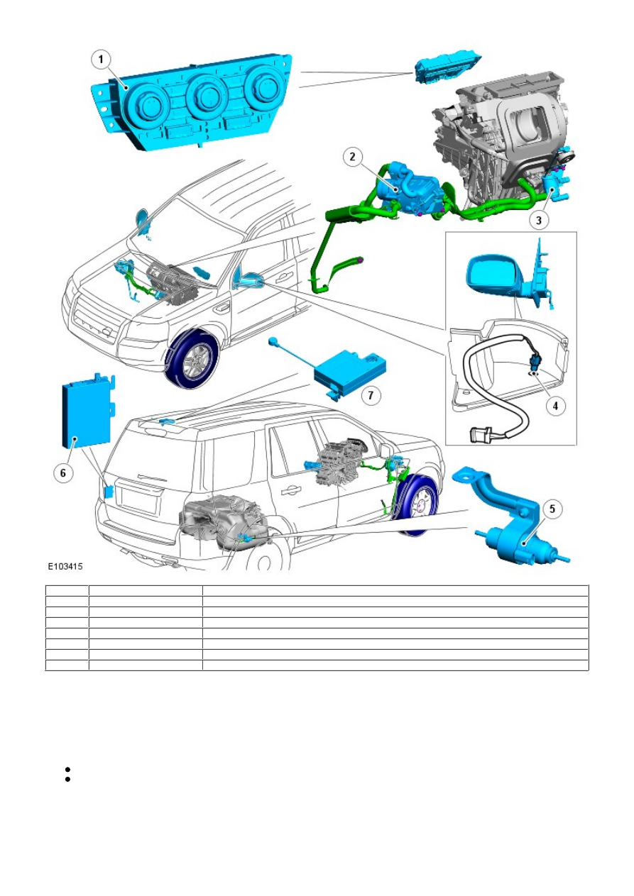
1
-
Automatic Temperature Control (ATC) module
2
-
Fuel Fired Booster Heater (FFBH)
3
-
Auxiliary coolant pump
4
-
Ambient air temperature sensor
5
-
Auxiliary fuel pump
6
-
FFBH Receiver
7
-
FFBH antenna matching unit
OVERVIEW
The Fuel fired Booster Heater (FFBH) is rated at 5 kW and compensates for the relatively low coolant temperatures
inherent in the diesel engine. The unit is located behind the Right Hand (RH) front fender splash shield and heats engine
coolant downstream of the heater core.
Operation of the FFBH is controlled by the Automatic Temperature Control (ATC) module via the medium speed Controller
Area Network (CAN) bus. Operation of the FFBH is influenced by:
Ambient air temperature
Engine coolant temperature.
The FFBH will operate if the ambient air temperature is lower than 5 °C (41 °F) and stop if ambient temperature reaches 8
°C (46 °F). Operation of the FFBH may also be inhibited if the fuel level drops below a predetermined level.
Remote Operation - Vehicles from 2009MY
On vehicles from 2009MY the FFBH has remote operation. The remote system includes the addition of a FFBH receiver,