Frelander 2. Manual - part 383
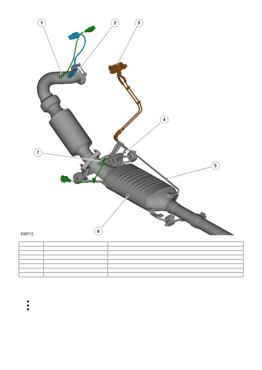
Item
Part Number
Description
1
-
Temperature sensor
2
-
HO2S
3
-
Differential pressure sensor
4
-
High pressure sensor pipe
5
-
Low pressure sensor pipe
6
-
Diesel particulate filter
7
-
Temperature sensor
The particulate emissions are the black fumes emitted from the diesel engine under certain load conditions. The emissions
are a complex mixture of solid and liquid components with the majority of the particulates being carbon microspheres on
which hydrocarbons from the engine's fuel and lubricant condense.
The DPF system comprises the following components:
Diesel particulate filter
DPF control software incorporated into the Engine Control Module (ECM)
Differential pressure sensor.
Diesel Particulate Filter
The DPF is located in the exhaust system, downstream of the catalytic converter. A major feature of the DPF is its ability
for regeneration. Regeneration is the burning of particulates trapped by the filter to prevent obstruction to the free flow of
exhaust gasses. The regeneration process takes place at calculated intervals and is not noticeable by the driver of the
vehicle.
Regeneration is most important, since an overfilled filter can damage the engine through excessive exhaust back pressure
and can itself be damaged or destroyed. The material trapped in the filter is in the most part carbon particles with some