Frelander 2. Manual - part 379
Exhaust System - I6 3.2L Petrol - Exhaust System
Description and Operation
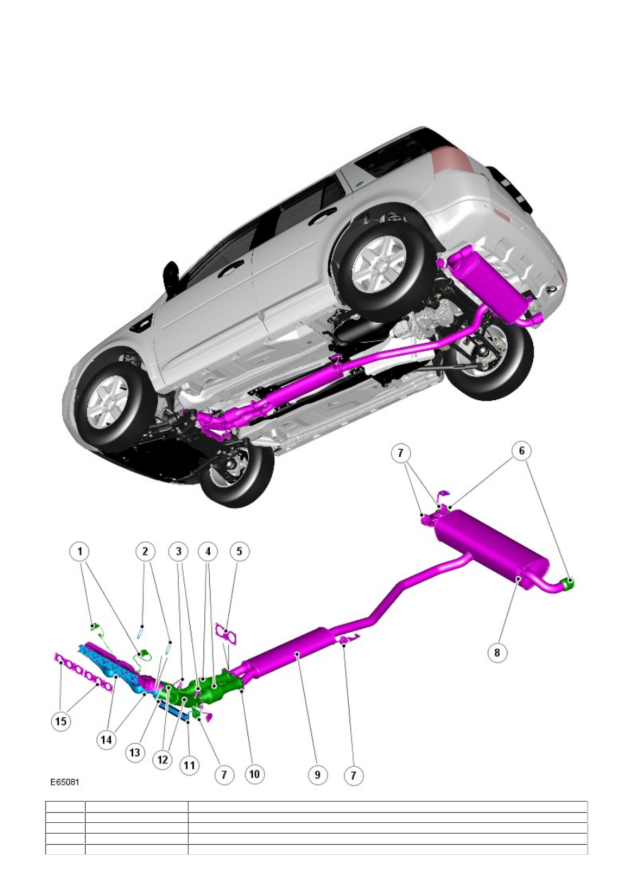
COMPONENT LOCATION
Item
Part Number
Description
1
-
Heated Oxygen Sensor (HO2S) - Pre-Catalyst (2 off)
2
-
Gasket (2 off)
3
-
HO2S - Post catalyst (2 off)
4
-
Flexible coupling