Frelander 2. Manual - part 371
13.
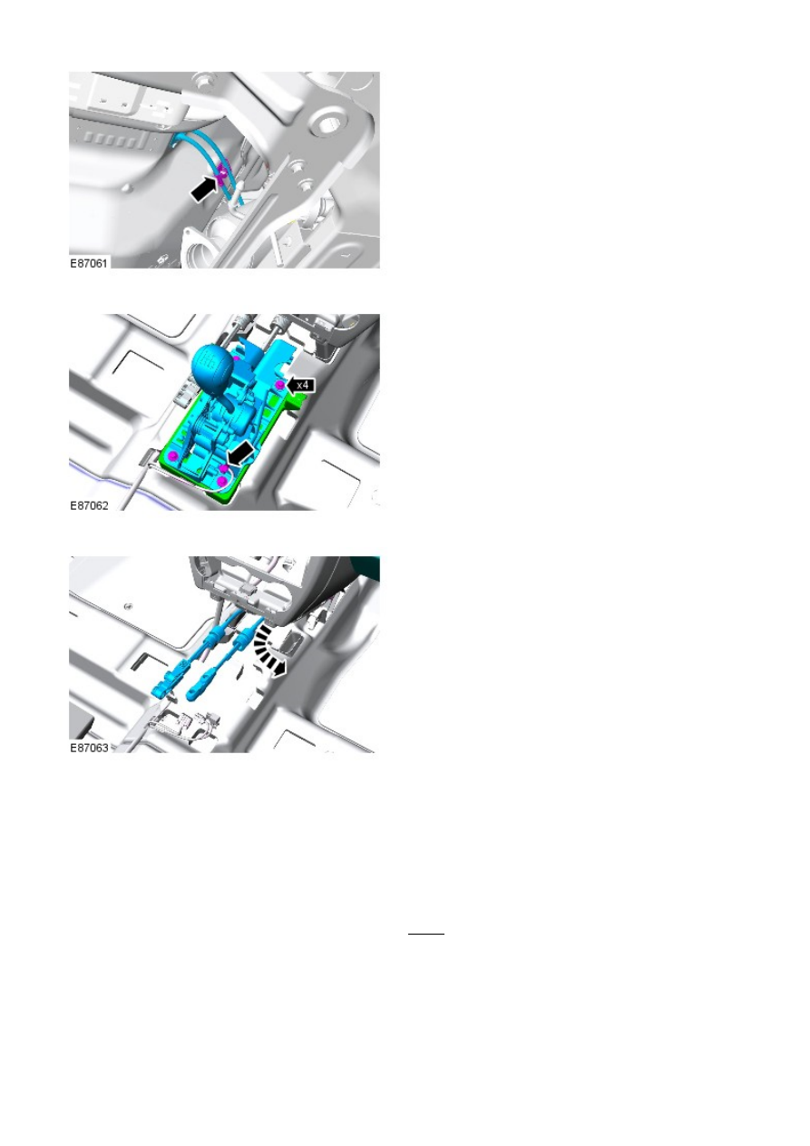
14.
15. NOTE: This step requires the aid of another
technician.
Remove the gearshift cable assembly.
15.
Installation
1. NOTE: This step requires the aid of another technician.
Install the gearshift cable assembly.
1.
Install the gearshift lever.
Torque: 10 Nm
2.
Secure the cables in the clips.
3.
Install the heat shield.
4.
Secure the selector cables.
5.