Frelander 2. Manual - part 310


  Index      Land Rover     Land Rover Frelander 2 - service repair manual 2006-2010 year


Search            


Content   ..  308  309  310  311   ..


Frelander 2. Manual - part 310


Electronic Engine Controls - TD4 2.2L Diesel - Electronic Engine Controls

Description and Operation

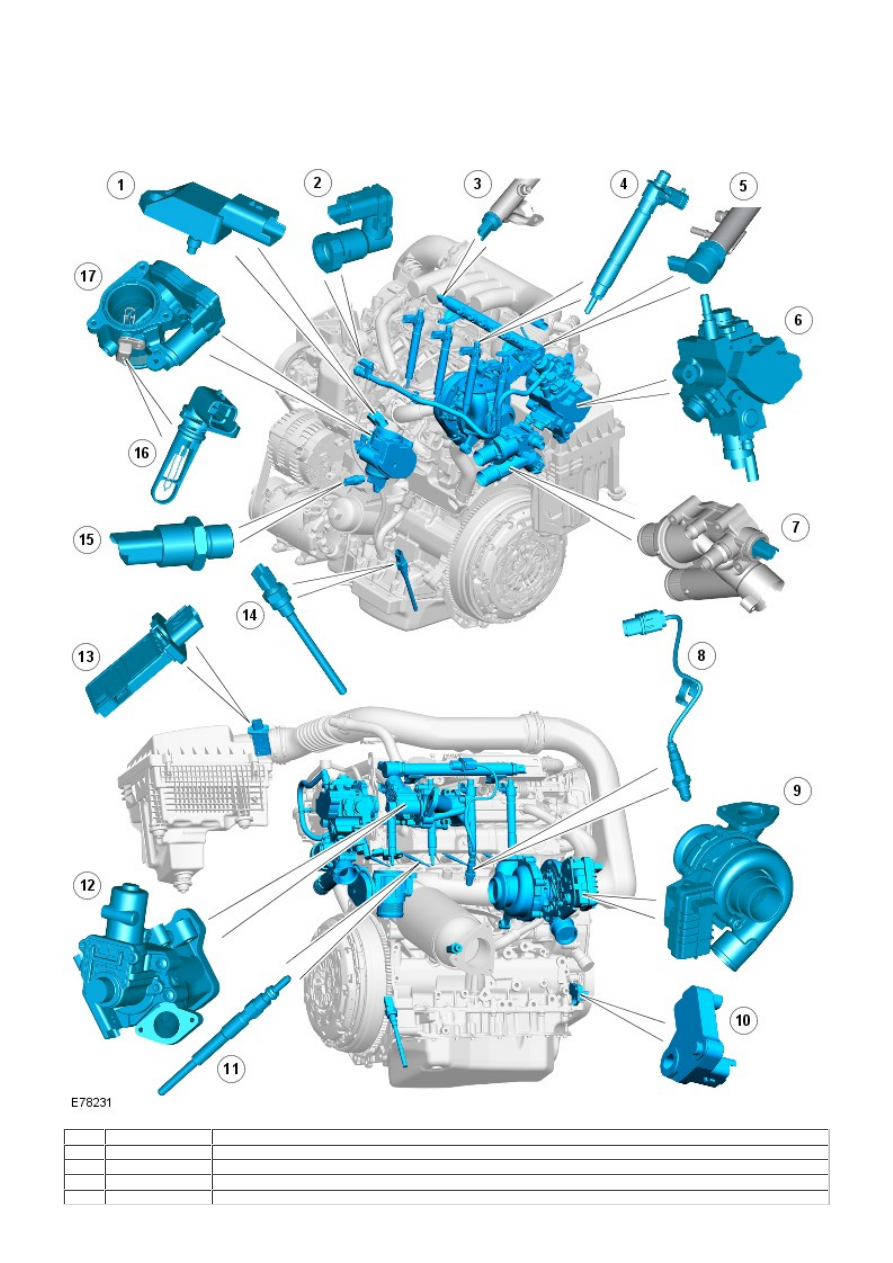
COMPONENT LOCATION SHEET 1 OF 2

Item

Part Number

Description

1

-

manifold absolute pressure (MAP) sensor

2

-

Fuel temperature sensor

3

-

Fuel rail pressure sensor

4

-

Injector (4 off)

5

-

Pressure control valve

6

-

Fuel pump (incorporating volume control valve)

7

-

engine coolant temperature (ECT) sensor

8

-

heated oxygen sensor (HO2S)

9

-

Variable nozzle turbocharger (VNT) controller

10

-

crankshaft position (CKP) sensor

11

-

Glow plugs (4 off)

12

-

exhaust gas recirculation (EGR) valve

13

-

mass air flow (MAF)/intake air temperature (IAT) sensor

14

-

Oil level and temperature sensor (Diesel Particulate Filter (DPF) vehicles only)

15

-

engine oil pressure (EOP) sensor

16

-

IAT sensor

17

-

Electric throttle

COMPONENT LOCATION SHEET 2 OF 2

• NOTE: left-hand (LH) drive vehicle shown, right-hand (RH) drive similar

Item

Part Number

Description

1

-

Differential pressure sensor (DPF vehicles only)

2

-

engine control module (ECM)

3

-

Stoplamp switch

4

-

accelerator pedal position (APP) sensor

5

-

Speed control inhibit switch

6

-

Start inhibit switch

7

-

Clutch switch

8

-

Downstream exhaust temperature sensor (DPF vehicles only)

9

-

battery junction box (BJB)

10

-

transmission control module (TCM) (automatic vehicles only)

11

-

air conditioning (A/C) compressor

12

-

Cooling fan control module

13

-

Upstream temperature sensor (DPF vehicles only)

14

-

Heated oxygen sensor

OVERVIEW

The TD4 diesel engine has an Electronic Diesel Control (EDC) engine management system. The system is controlled by an
ECM which is able to monitor, adapt and precisely control the fuel injection. The ECM uses multiple sensor inputs and
precision control of actuators to achieve optimum performance during all driving conditions.

The ECM controls fuel delivery to all 4 cylinders via a common rail injection system. The common rail system uses a fuel
rail to accumulate highly pressurized fuel and feed the 4, electronically controlled injectors. The fuel rail is located in close
proximity to the injectors, which assists in maintaining full system pressure at each injector at all times.

The ECM uses the drive by wire principle for acceleration control. Accelerator pedal demand is communicated to the ECM by
2 potentiometers located in a throttle position sensor. The ECM uses the 2 signals to determine the position, rate of
movement and direction of movement of the pedal. The ECM then uses this data, along with other engine information from
other sensors, to achieve the optimum engine response.

The ECM processes information from the following input sources:

camshaft position (CMP)
CKP
Manifold air temperature and pressure
Engine coolant temperature
Oil temperature
Intake air flow and temperature
Fuel temperature

The ECM outputs controlling signals to the following sensors and actuators:

Fuel injectors (4 off)
Cooling fan control module
Electric throttle valve
Electronic vane controlled turbocharger
Port deactivation
Fuel pressure control valve
Fuel volume control valve
EGR
Glow plugs (4 off).

CONTROL DIAGRAM SHEET 1 OF 2

• NOTE: A = Hardwired


Content   ..  308  309  310  311   ..