Frelander 2. Manual - part 284


  Index      Land Rover     Land Rover Frelander 2 - service repair manual 2006-2010 year


Search            


Content   ..  282  283  284  285   ..


Frelander 2. Manual - part 284


module)

, regulates the amount of exhaust gases recirculated into the air intake system. The 

ECM

 uses signals from

various engine sensors and calculates a response based on the embedded software algorithm to control exhaust gas
recirculation. The 

ECM

 transmits this control signal to the valve's actuator, which is closed-loop controlled with the mass

air flow (MAF) sensor providing the feedback to the 

ECM

.

COMPONENT DESCRIPTION

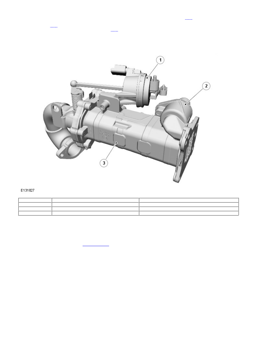
Exhaust Gas Recirculation (EGR) Valve and Cooler Assembly

Item

Part Number

Description

1

-

Actuator

2

-

Coolant outlet

3

-

Cooler

The EGR valve and cooler assembly is located on the RH side of the cylinder head above the exhaust manifold, and
secured with 4 fixings. An inlet pipe connects the EGR cooler to the exhaust manifold. A gas transfer tube is routed across
the engine and connects the EGR valve outlet to the intake manifold housing.

A pipe on the EGR cooler body connects to the climate control heater outlet hose, and provides the coolant supply to the
EGR cooler. The EGR cooler outlet connects to the coolant rail, located on the RH side of the engine. The coolant rail is
connected between the thermal control module and the coolant pump rear housing.
For additional information, refer to: 

Engine Cooling

 (303-03A Engine Cooling - I6 3.2L Petrol, Description and Operation).

The EGR is controlled by the ECM, and is enabled when the engine meets the correct operating temperatures and under
cruising conditions.

Oil Separator

The crankcase ventilation oil separator is also connected to the oil filler tube, located at the rear LH side of the engine. Oil
for replenishing the system passes through the oil separator and return hose, and into the oil pan. An oil baffle plate is
installed in the oil pan housing to reduce oil aeration and splash.

Engine Emission Control - TD4 2.2L Diesel - Engine Emission Control

Diagnosis and Testing

Principles of Operation

For a detailed description of the engine emission control systems, refer to the relevant Description and Operation section
in the workshop manual.
REFER to: 

Engine Emission Control

 (303-08B Engine Emission Control - TD4 2.2L Diesel, Description and Operation).

Inspection and Verification

CAUTION: Diagnosis by substitution from a donor vehicle is NOT acceptable. Substitution of control modules does

not guarantee confirmation of a fault, and may also cause additional faults in the vehicle being tested and/or the donor
vehicle.

1. Verify the customer concern.

1.

2. Visually inspect for obvious signs of mechanical or electrical damage.

2.

Visual Inspection

Mechanical

Electrical

EGR valve
EGR pipes/hoses
Vacuum system
Engine breather system

Wiring harness
Electrical connector(s)
Fuses(s)

3. If an obvious cause for an observed or reported concern is found, correct the cause (if possible) before

proceeding to the next step

3.

4. If the cause is not visually evident, verify the symptom and refer to the Symptom Chart, alternatively, check for

Diagnostic Trouble Codes (DTCs) and refer to the DTC Index.

4.

Symptom Chart

Symptom

Possible Cause

Action

Rough idle, lack of power under acceleration,
excessive fuel consumption, excessive black
smoke

EGR valve stuck

Check EGR valve for correct operation.
Check for related DTCs and refer to the DTC
Index

Excessive engine blow-by/crankcase pressure

Engine breather system
blocked/restricted
Excessive engine wear

Check engine breather system for
blockage/restriction. Check for excessive
engine wear
REFER to: 

Engine

 (303-00 Engine System -

General Information, Diagnosis and
Testing).

DTC Index

• NOTE: If the control module or a component is suspect and the vehicle remains under manufacturer warranty, refer to the
Warranty Policy and Procedures manual (section B1.2), or determine if any prior approval programme is in operation, prior
to the installation of a new module/component.

• NOTE: Generic scan tools may not read the codes listed, or may read only five digit codes. Match the five digits from the
scan tool to the first five digits of the seven digit code listed to identify the fault (the last two digits give additional
information read by the manufacturer approved diagnostic system).

• NOTE: When performing voltage or resistance tests, always use a digital multimeter (DMM) accurate to three decimal
places, and with an up-to-date calibration certificate. W hen testing resistance always take the resistance of the DMM
leads into account.

• NOTE: Check and rectify basic faults before beginning diagnostic routines involving pinpoint tests.

• NOTE: Inspect connectors for signs of water ingress, and pins for damage and/or corrosion.

• NOTE: If DTCs are recorded and, after performing the pinpoint tests, a fault is not present, an intermittent concern may
be the cause. Always check for loose connections and corroded terminals.

DTC

Description

Possible Cause

Action

P040500 Exhaust Gas Recirculation

Sensor A Circuit Low

EGR Valve position sensor
voltage below lower limit

Carry out the pinpoint tests associated with
this DTC using the manufacturer approved
diagnostic system

P040600 Exhaust Gas Recirculation

Sensor A Circuit High

EGR Valve position sensor
voltage above upper limit

Carry out the pinpoint tests associated with
this DTC using the manufacturer approved
diagnostic system

P042E00 Exhaust Gas Recirculation

Control Stuck Open

EGR Valve stuck during normal
engine running - attempt to
unstick valve unsuccessful

Check/clear EGR valve from
obstruction/sticking

DTC

Description

Possible Cause

Action

P042F00 Exhaust Gas Recirculation

Control Stuck Closed

EGR Valve stuck during normal
engine running - attempt to
unstick valve unsuccessful
EGR Valve stuck during after run
tests

Check/clear EGR valve from
obstruction/sticking

P048900 Exhaust Gas Recirculation

Control Circuit Low

EGR Valve position deviation -
valve stuck open

Check/clear EGR valve from
obstruction/sticking

P049000 Exhaust Gas Recirculation

Control Circuit High

EGR Valve position deviation -
valve stuck closed

Check/clear EGR valve from
obstruction/sticking

P140200 Exhaust Gas Recirculation

Metering Orifice
Restricted

EGR valve closed position offset
difference with first learning too
large
EGR valve closed position offset
difference with previous learning
too large

Check/clear EGR valve from
obstruction/sticking, clear DTC and re-test. If
DTC remains, install new EGR valve

P148700 Exhaust Gas Recirculation

Check Solenoid Circuit

EGR valve H-Bridge driver error

Clear the DTC and re-test. If the DTC
remains, install a new ECM

P154500 Exhaust Gas Recirculation

High Side Control Circuit /
Open

Exhaust gas recirculation control
circuit 1 (positive) - open circuit
Exhaust gas recirculation control
circuit 2 (negative) - open circuit

Refer to electrical circuit diagrams and check
exhaust gas recirculation control circuit for
open circuit

P154611 Exhaust Gas Recirculation

High Side Control Circuit
Low

Exhaust gas recirculation control
circuit 1 (positive) - short to
ground
Exhaust gas recirculation control
circuit 2 (negative) - short to
ground

Refer to electrical circuit diagrams and check
exhaust gas recirculation control circuit for
short to ground

P154712 Exhaust Gas Recirculation

High Side Control Circuit
High

Exhaust gas recirculation control
circuit 1 (positive) - short to
power
Exhaust gas recirculation control
circuit 2 (negative) - short to
power

Refer to electrical circuit diagrams and check
exhaust gas recirculation control circuit for
short to power


Content   ..  282  283  284  285   ..