Frelander 2. Manual - part 193


  Index      Land Rover     Land Rover Frelander 2 - service repair manual 2006-2010 year


Search            


Content   ..  191  192  193  194   ..


Frelander 2. Manual - part 193


12

-

Dual mass flywheel (manual transmission vehicles)

13

-

Bolt (8 off)

14

-

Torque converter flex-plate (automatic transmission vehicles)

15

-

Main bearing lower half shell (4 off)

16

-

Lower thrust washer (2 off)

17

-

Main bearing half cap (5 off)

18

-

Oil pump

19

-

Oil level gage tube (lower)

20

-

Bolt

21

-

Locating dowel

22

-

Oil pan housing

23

-

Oil pan housing bolt (20 off)

24

-

Oil pan captive bolt (21 off)

25

-

Oil drain plug seal

26

-

Oil drain plug

27

-

Oil pan

28

-

Oil temperature sensor

29

-

Screw (2 off)

30

-

Oil level gage tube (upper)

31

-

Oil level gage

32

-

Oil pump drive chain

33

-

Crankshaft pulley bolt

34

-

Plain washer

35

-

Crankshaft pulley and torsional vibration damper

36

-

CKP sensor target ring

37

-

Woodruff key (2 off)

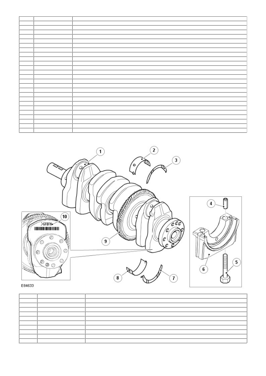
Crankshaft and Main Bearings

Item

Part Number

Description

1

-

Crankshaft

2

-

Main bearing upper half shell (4 off)

3

-

Upper thrust washer (2 off)

4

-

No. 1 main bearing cap locating dowel (2 off)

5

-

Main bearing cap bolt (10 off)

6

-

Main bearing half cap (5 off)

7

-

Lower thrust washer (2 off)

8

-

Main bearing lower half shell (4 off)

9

-

Counter-balance shaft drive gear

10

-

Main bearing classification markings

The crankshaft is manufactured from steel and formed with 5 main bearing and 4 connecting rod big-end journals. The
main bearing journals locate in the cylinder block main bearing housings, and are clamped by the 5 main bearing half caps.
Each main bearing half cap is stamped with the corresponding cylinder number for identification. The main bearing half cap
identified with '1F' must be positioned at the transmission end of the engine (No. 1 end).

Lateral movement of the crankshaft is restricted by 4 half-round thrust washers, located on both sides of No. 2 main
bearing. Lubrication grooves are formed on the thrust washers and must face toward the main bearing. The crankshaft
end-float must be between 0.07 mm (0.003 in) and 0.32 mm (0.013 in).

Each main bearing housing and half cap contains an upper and lower bearing half shell manufactured from aluminum/tin.
The upper half shells are formed with a drilling and annular groove to transfer pressurized oil from the main bearing,
through crankshaft drillings to the connecting rod big-end bearings.

The main bearing half caps and the upper and lower bearing half shells are formed with a lug. The lug allows correct
alignment of the bearing and cap, and prevents radial movement of the bearing.

To maintain the correct crankshaft main bearing clearance, the main bearing half shells are available in varying thickness.
The upper main bearing half shell is only available in 1 size; the lower main bearing half shell is available in 5 sizes. Both
the upper and lower main bearing half shells are color coded for identification. To determine the correct size of bearing half
shell, classification markings on the crankshaft front face and on the cylinder block front face are used in conjunction with
a bearing size chart.

For further details on main bearing half shell installation, refer to the relevant Service Repair Procedures (SRP).

A drive gear is formed as a 'shrink-fit' on No. 3 crankshaft web, located between No. 2 main bearing journal and No. 2
connecting rod big-end journal. The drive gear is single helical cut and provides the drive to the counter-balance shaft
gears. An 18 teeth spur gear is located on the front of the crankshaft, behind the front crankshaft sealing plate. The spur
gear provides the drive to the oil pump assembly via a single row chain, and is locked to the crankshaft with a woodruff
key.

A toothed gear mounted to the front of the crankshaft provides the drive for the camshaft timing belt. The drive gear
contains 21 teeth and is keyed to the crankshaft with a woodruff key.

Crankshaft Oil Seals

Item

Part Number

Description

1

-

Crankshaft front seal adaptor

2

-

Crankshaft front oil seal

3

-

Crankshaft rear oil seal

The crankshaft is sealed to the cylinder block at the front and rear ends with lip type oil seals. Each seal is pressed into
the corresponding front and rear cylinder block housing, with the lip facing the crankshaft. Special tools are required for
removal and installation of the crankshaft seals.

Connecting Rods and Pistons

Item

Part Number

Description

1

-

Upper compression ring

2

-

Lower compression ring

3

-

Oil control 'scraper' ring

4

-

Gudgeon pin

5

-

Gudgeon pin circlip (2 off)

6

-

Piston and connecting rod assembly

7

-

Connecting rod big-end

8

-

Connecting rod shaft

9

-

Connecting rod small-end

10

-

Small-end bush

11

-

Piston crown cooling channel

12

-

Piston bush (2 off per piston)

The connecting rods are manufactured from forged steel with an 'I' beam shaft construction to provide high strength and
durability. The connecting rod small-end is narrowed on each side to form a tapered head. The taper improves the
distribution of force between the piston and connecting rod during the combustion stroke. A bronze bush is installed in the
small-end, and formed with an internal groove to allow the flow of lubricating oil around the bush.

The connecting rod big-end is cut and machined at the joint to form a bearing housing and bearing cap that is secured by 2
bolts. The cylinder position is stamped on adjoining sides of the joint to identify matching connecting rods and bearing
caps. A half shell bearing is installed in each half of the connecting rod big-end. The connecting rod bearing housings and
shell bearings are manufactured with a lug that correctly aligns the bearing in the housing, and prevents radial movement
of the bearing shells. During installation the lugs must face toward the LH side (oil filter side) of the engine.

To maintain the correct crankshaft big-end bearing clearance, the half shell bearings are available in varying thickness. The
lower bearing half shell is only available in 1 size; the upper bearing half shell is available in 3 sizes.


Content   ..  191  192  193  194   ..