Frelander 2. Manual - part 162
Engine - I6 3.2L Petrol - Engine
Diagnosis and Testing
Principles of Operation
For a detailed description of the engine system, refer to the relevant Description and Operation section in the workshop
manual.
REFER to:
Engine
(303-01A Engine - I6 3.2L Petrol, Description and Operation).
Inspection and Verification
1. Verify the customer concern.
1.
2. Visually inspect for obvious signs of mechanical or electrical damage.
2.
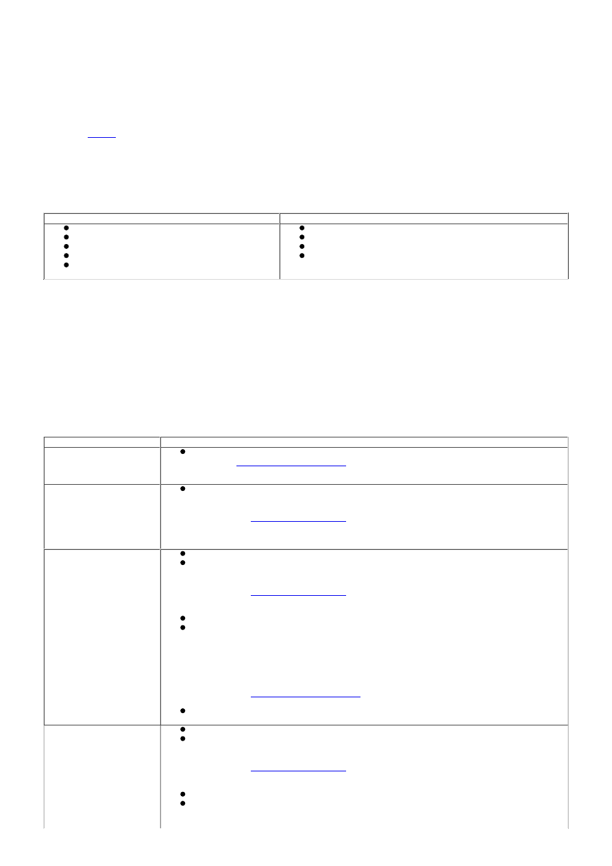
Visual Inspection
Mechanical
Electrical
Coolant leaks
Oil leaks
Leaks in the fuel system
Visibly damaged or worn parts
Loose or missing fixings
Fuses
Loose or corroded electrical connectors
Harnesses
Sensors
3. If an obvious cause for an observed or reported concern is found, correct the cause (if possible) before
proceeding to the next step
3.
4. If the cause is not visually evident, verify the symptom and refer to the Symptom Chart.
4.
Symptom Chart
• NOTE: If an engine is suspect, when the vehicle remains under the Manufacturers warranty refer to the Warranty Policy
and Procedure manual (section B1.2), or determine if any prior approval programme is in operation, prior to the installation
of a new engine.
• NOTE: Due to the possibility of loose carbon, that has become trapped between the valve face and seat, effecting the
pressure readings, when carrying out a compression test and some cylinders are found to have low pressures, install the
spark plugs, road test the vehicle and re-test the suspect cylinders. If the correct pressures are restored, no further action
is required.
Symptom
Action
All engine related issues
Check ECM for Diagnostic Trouble Codes (DTCs) and refer to DTC Index.
REFER to:
Electronic Engine Controls
(303-14A Electronic Engine Controls - I6 3.2L
Petrol, Diagnosis and Testing).
Difficult to start hot and
cold
Carry out general engine checks:
- Compression test. Refer to component tests in this section.
- Valve clearances.
REFER to:
Valve Clearance Check
(303-01A Engine - I6 3.2L Petrol, General
Procedures).
- Spark plug condition and color
Poor idle
Ensure the air intake system is free from leaks
Carry out general engine checks:
- Compression test. Refer to component tests in this section.
- Valve clearances.
REFER to:
Valve Clearance Check
(303-01A Engine - I6 3.2L Petrol, General
Procedures).
- Spark plug condition and color
Check for collapsed catalytic converter/blocked exhaust system
Check long and short term fuel trim datalogger signals
- Readings up to 10%: may be considered as acceptable if the readings are equal
bank to bank
- Positive readings of between 10-20%: check for air leaks in air intake system
- Negative readings of between 10-20%: check for over fuelling e.g. leaking
injectors, high fuel pressure
- Readings above 20%: check for DTCs and refer to DTC Index.
REFER to:
Electronic Engine Controls
(303-14A Electronic Engine Controls - I6 3.2L
Petrol, Diagnosis and Testing).
Carry out a vacuum gauge check. Refer to component tests in this section.
Insufficient
power/Insufficient
compression
Ensure the air intake system is free from leaks
Carry out general engine checks:
- Compression test. Refer to component tests in this section.
- Valve clearances.
REFER to:
Valve Clearance Check
(303-01A Engine - I6 3.2L Petrol, General
Procedures).
- Spark plug condition and color
Check for collapsed catalytic converter/blocked exhaust system
Check long and short term fuel trim datalogger signals
- Readings up to 10%: may be considered as acceptable if the readings are equal
bank to bank