Frelander 2. Manual - part 154
Item
Part Number
Description
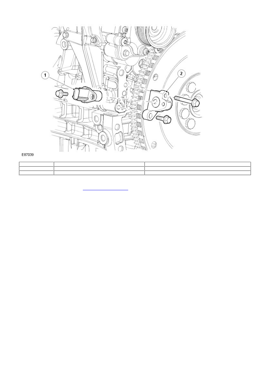
1
-
CKP sensor
2
-
Sensor bracket
The Crankshaft Position (CKP) sensor is located at the rear of the intake side of the cylinder block. The sensor provides an input of
engine crankshaft speed and position. The sensor works on the principle of the Hall effect and scans a trigger wheel (magnetic
disc) on the flywheel
For additional information, refer to:
Electronic Engine Controls
(303-14A Electronic Engine Controls - I6 3.2L Petrol, Description and
Operation).
.
Knock Sensors