Frelander 2. Manual - part 149


  Index      Land Rover     Land Rover Frelander 2 - service repair manual 2006-2010 year


Search            


Content   ..  147  148  149  150   ..


Frelander 2. Manual - part 149


6.

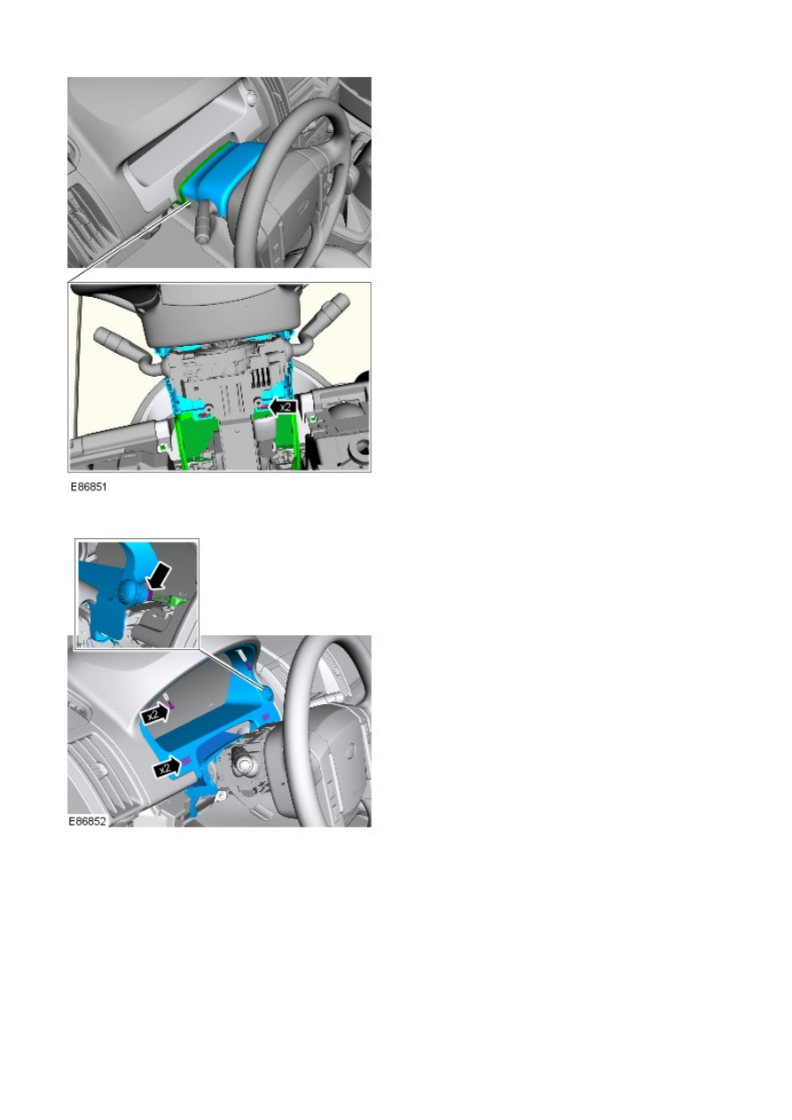
7. NOTE: Take extra care when releasing the clips.

Remove the instrument cluster surround.

7.

Remove the ignition switch.

8.

Installation

To install, reverse the removal procedure.

1.

Steering Column Switches - Steering Column Lock Module

Removal and Installation

Removal

• NOTE: On vehicles built from VIN 091770 the steering column lock module may be a non-functional component.

• NOTE: The steering column lock module is retained with 2 X 6mm patch locked, tamper proof bolts.

• NOTE: Removal steps in this procedure may contain installation details.

Disconnect the battery ground cable.

Refer to: 

Specifications

 (414-00 Battery and Charging System -

General Information, Specifications).

1.

Remove the steering column.

Refer to: 

Steering Column

 (211-04 Steering Column, Removal and

Installation).

2.

3. NOTE: Using a suitable stud extraction tool, remove
the tamper proof bolts .

3.

Installation

1. 

CAUTION: Tighten the new tamper proof bolts until the

hexagon head shears.

To install, reverse the removal procedure.

1.

Using the Land Rover approved diagnostic system, calibrate a new
module.

2.

Engine System - General Information - Engine

Diagnosis and Testing

For additional information. REFER to:

Engine

 (303-01A Engine - I6 3.2L Petrol, Diagnosis and Testing),

Engine

 (303-01B Engine - TD4 2.2L Diesel, Diagnosis and Testing).


Content   ..  147  148  149  150   ..