Frelander 2. Manual - part 147
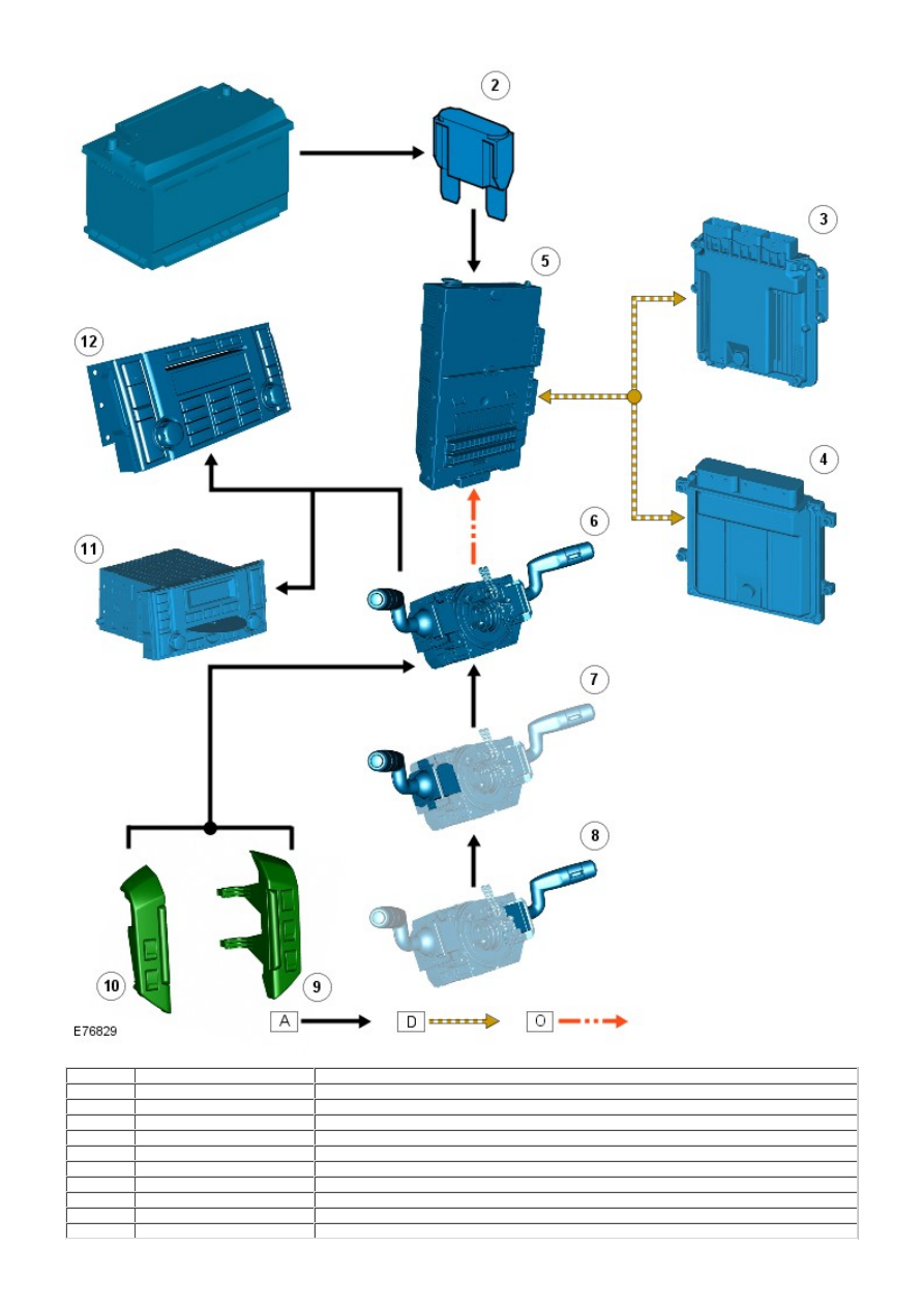
Item
Part Number
Description
1
-
Battery
2
-
Mega fuse 18
3
-
Engine control module (ECM) (Diesel)
4
-
Engine control module (ECM) (petrol)
5
-
Central junction box (CJB)
6
-
Clockspring
7
-
Steering column LH multifunction switch
8
-
Steering column RH multifunction switch
9
-
RH audio control switches
10
-
LH speed control switches