Frelander 2. Manual - part 117
6.
7.
Repeat the above procedure for the other side.
8.
Installation
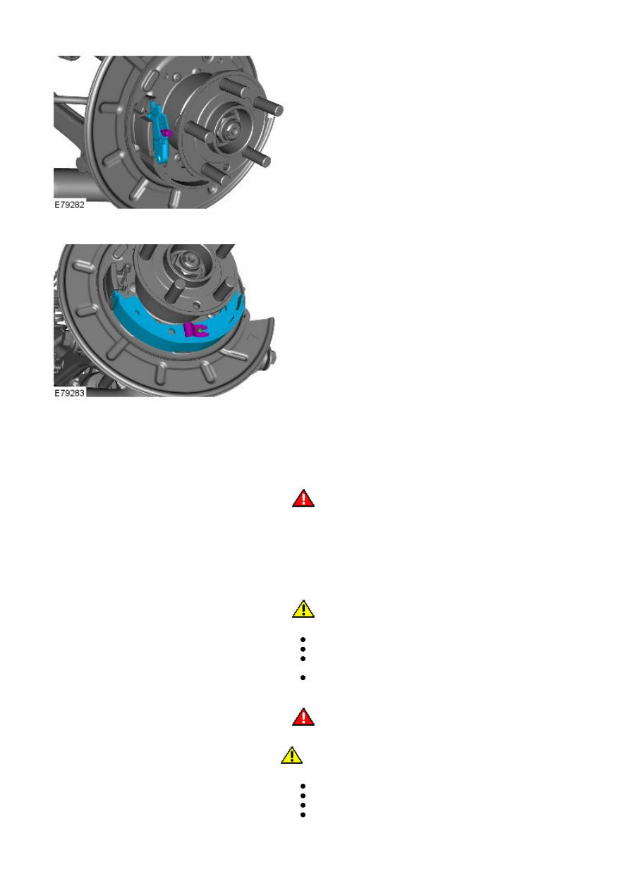
1.
WARNING: Do not use compressed air to clean brake
components. Dust from friction materials can be harmful if inhaled.
Clean the backing plate and apply grease to the brake shoe
contacts.
1.
Clean the adjuster and set it to its minimum extension.
2.
3.
CAUTION: Make sure the brake shoe spring is not over
stretched.
Install the secondary brake shoe.
Connect the parking brake cable.
Connect the parking brake cable retaining spring to the brake
shoe lever, making sure the spring is not twisted.
Install the hold-down spring and retaining pin.
3.
4.
WARNING: Make sure the return spring and the adjuster
spring are correctly installed to the primary shoe.
CAUTION: Make sure the brake shoe spring is not over
stretched.
Install the primary brake shoe.
Install the spreader plate and the spring.
Install the return spring.
Install the hold-down spring and retaining pin.
4.