Frelander 2. Manual - part 106


  Index      Land Rover     Land Rover Frelander 2 - service repair manual 2006-2010 year


Search            


Content   ..  104  105  106  107   ..


Frelander 2. Manual - part 106


3

-

Dust shield

4

-

Dust shield retaining screw (3 off)

5

-

Brake disc

6

-

Brake disc retaining screw

7

-

Outer anti-squeal shim

8

-

Outer brake pad

9

-

Inner brake pad

10

-

Inner anti-squeal shim

11

-

Caliper housing spring

12

-

Fixed carrier

13

-

Caliper piston seal

14

-

Caliper piston

15

-

Sliding caliper

16

-

Bushed bolt rubber boot (2 off)

17

-

Bushed bolt (2 off)

18

-

Bushed bolt dust cap (2 off)

19

-

Caliper bleed screw

20

-

Bleed screw cap

21

-

Flexible hose

22

-

Fixed carrier retaining bolt (2 off)

23

-

Front Left-Hand (LH) wheel knuckle

OVERVIEW

The front brake assembly features a ventilated brake disc and cast-iron sliding caliper with single acting piston.
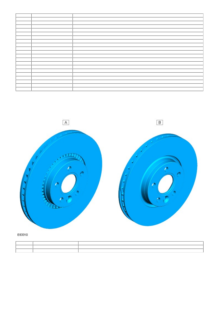
BRAKE DISC

Item

Part Number

Description

A

-

Front brake disc - i6 gasoline vehicle

B

-

Front brake disc - TD4 diesel vehicle

The brake disc installed to the 3.2 liter i6 gasoline vehicle is 316 x 28 mm (12.44 x 1.10 in) diameter. The brake disc
installed to the 2.2 liter TD4 diesel vehicle is 300 x 28 mm (11.81 x 1.10 in) diameter. The brake disc is secured to the
wheel knuckle hub with a single screw and is also retained by the 5 wheel securing nuts.

Both types of front brake disc are manufactured with ventilation channels, allowing the disc to achieve high levels of
thermal stability even during severe braking.

The disc is cooled as the forward motion of the vehicle draws air through the ventilation channels, and across the surfaces
of the disc.

CALIPER ASSEMBLY

Item

Part Number

Description

A

-

Front brake caliper - i6 gasoline vehicle

B

-

Front brake caliper - TD4 diesel vehicle

The caliper assembly comprises a fixed carrier and sliding caliper. The fixed carrier is mounted to straddle the brake disc
and is attached to the wheel knuckle with 2 bolts. The fixed carrier provides the location for 2 brake pads that are
mounted on either side of the brake disc, and is formed with guide channels that allow the brake pads to slide toward the
disc surface.

• NOTE: The 2 fixed carrier retaining bolts are pre-applied with a thread locking adhesive and must not be re-used during
maintenance. New fixed carrier retaining bolts must be used and the original bolts discarded.

The sliding caliper is mounted over the fixed carrier and retains the 2 brake pads within the caliper assembly. The sliding
caliper is secured to the fixed carrier with 2 bushed bolts, and is formed with a hydraulic chamber containing a 60 mm
(2.36 in) diameter piston and annular seal.

The sliding caliper is connected via a flexible hose to the brake system hydraulic circuit, and also incorporates a bleed
screw for maintenance purposes.

The 2 bushed bolts are machined with a smooth surface and are protected from dirt and moisture ingress with a collapsible
rubber boot. The bushed bolts allow the sliding caliper limited lateral movement along the fixed carrier.

A housing spring is located on the outer side of the brake disc, and is connected with formed hooks between the fixed
carrier and sliding caliper. During operation of the brake, the spring is tensioned as the sliding caliper moves toward the
brake disc. The spring assists to move the sliding caliper away from the brake disc as the brake is released.

An anti-squeal shim is installed on the outside edge of each brake pad and reduces Noise, Vibration and Harshness (NVH)
from the brake components during operation.

The brake pads are not installed with pad wear sensors.

BRAKE DUST SHIELD

A formed brake dust shield is located between the wheel knuckle and brake disc, and is secured to the knuckle with 3
screws.

The brake dust shield is handed to the relevant side of the vehicle and protects the brake components from cross axle
stone throws. The brake dust shield also prevents debris and brake dust from spreading to other parts of the vehicle.

PRINCIPLES OF OPERATION

Brake Application

As the brake pedal is applied, initial hydraulic pressure is felt in the sliding caliper chamber causing the piston to extend
toward the brake disc. The moving piston contacts the inner brake pad, forcing the pad along the fixed carrier guide
channels and into contact with the inner side of the brake disc.

As the piston extends from the caliper chamber, it passes through an internal annular seal located within the caliper

chamber. The movement of the piston distorts the shape of the seal and consequently, the seal applies pressure on the
piston outer surface.

The sliding caliper now reacts and commences to slide along the 2 bushed bolts, in the opposite direction to the extending
piston. The sliding caliper contacts the outer brake pad, forcing the pad along the fixed carrier guide channels and into
contact with the outer side of the brake disc. The housing spring that is attached between the fixed carrier and sliding
caliper is tensioned as the sliding caliper moves toward the brake disc.

With both brake pads now in full contact with the brake disc and hydraulic pressure acting on the piston, no further
movement of the piston and sliding caliper is possible. The force created by the piston and caliper acting against the brake
pads increases rapidly, trapping the brake disc and slowing the vehicle.

Brake Release

As the brake pedal is released, hydraulic pressure in the caliper chamber collapses and force is no longer applied to the
brake pads. The brake pads are moved slightly outwards by the action of the rotating brake disc, and the caliper internal
annular seal returns to the normal shape. As the seal moves it grips on the piston outer surface and withdraws the piston
into the chamber, sufficiently to provide the necessary pad to disc clearance.

This action prevents the piston from holding the inner brake pad against the disc, and also enables the piston to protrude
further from the caliper chamber to compensate for brake pad wear.

With no pressure being applied to the hydraulic system, the housing spring tension is also relieved and the spring returns
to the normal position. As the housing spring moves, the attached sliding caliper is moved away from the outer side of the
disc to provide the necessary clearance between the outer brake pad and the brake disc.

Front Disc Brake - Front Disc Brake

Diagnosis and Testing

For additional information.
REFER to: 

Brake System

 (206-00 Brake System - General Information, Diagnosis and Testing).


Content   ..  104  105  106  107   ..