Frelander 2. Manual - part 100


  Index      Land Rover     Land Rover Frelander 2 - service repair manual 2006-2010 year


Search            


Content   ..  98  99  100  101   ..


Frelander 2. Manual - part 100


2. CAUTIONS:

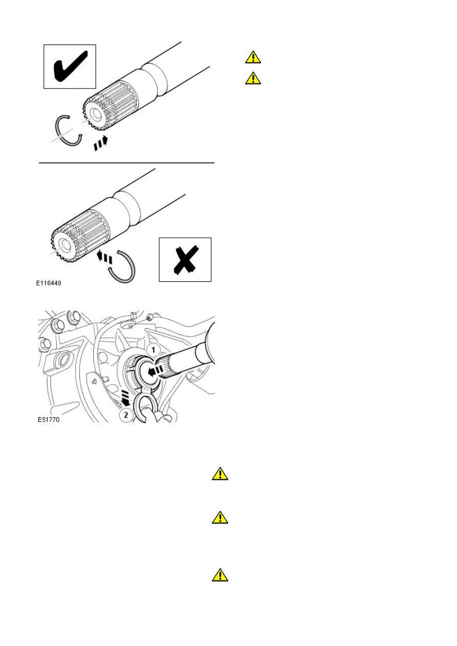
 Take extra care not to damage the seal.

 Make sure that the snap ring is installed from the

end of the halfshaft. Failure to follow this instruction
may result in damage to the vehicle.

Install a new snap ring to the rear halfshaft and with
assistance, connect the inner CV joint to the
differential.

2.

3. NOTE: The oil seal protector is designed to break
into two pieces.

Remove and discard the rear halfshaft oil seal
protector.

3.

W ith assistance, install the rear halfshaft to the hub.

4.

5. 

CAUTION: Only tighten the nut finger tight at this stage.

Install a new rear halfshaft nut, do not fully tighten at this stage.

5.

6. 

CAUTION: Only tighten the nuts and bolts finger tight at

this stage.

Connect both lower arms to the hub assembly, do not fully tighten
at this stage.

6.

7. 

CAUTION: Only tighten the nut and bolt finger-tight at this

stage.

Connect the trailing arm to the hub assembly, do not fully tighten at
this stage.

7.

Stage 1:
Stage 2:

Secure the parking brake cable.

8.

Support the weight of the vehicle using a jack under the rear hub.

9.

10. CAUTIONS:

 Nuts and bolts must be tightened with the weight of the

vehicle on the suspension.

 Do not use air tools to install the nut. Failure to follow this

instruction may result in damage to the component.

Tighten both lower arm nuts and bolts.

Torque: 175 Nm
Tighten the trailing arm nut and bolt.

Torque: 270 Nm
Tighten the rear halfshaft nut.

Torque:

330 Nm
30°

Stake the hub nut.

10.

Install the stabilizer bar link.

Refer to: 

Rear Stabilizer Bar Link

 (204-02 Rear Suspension, Removal

and Installation).

11.

Install the wheel and tire.

Refer to: 

Wheel and Tire

 (204-04 W heels and Tires, Removal and

Installation).

12.

13. 

CAUTION: Do not fill the differential with lubricant up to

the filler plug. The filler plug is only used to fill the differential with
lubricant, and not to act as a level indicator.

Fill the differential with the correct amount of lubricant.

13.

Rear Drive Halfshafts - Inner Constant Velocity (CV) Joint Boot

Removal and Installation

Special Tool(s)

303-D121
Puller, General Purpose

Removal

1. 

WARNING: Make sure to support the vehicle with axle

stands.

Raise and support the vehicle.

1.

Remove the halfshaft.

Refer to: 

Rear Halfshaft LH

 (205-05 Rear Drive Halfshafts, Removal

and Installation).

2.

3. NOTE: Discard the retaining clips.

3.

4.

5. NOTE: Discard the retaining clip.

5.

Special Tool(s): 

303-D121

6.

Installation

1. 

CAUTION: Extreme cleanliness must be exercised when

handling these components.

Clean and inspect the components for deterioration.

1.

Install the inner CV boot onto the halfshaft.

2.

3. NOTE: Install a new retaining clip.

Install the inner CV joint inner onto the halfshaft.

3.

4. 

CAUTION: Make sure that these components are installed to

the noted removal position.

Install the inner CV joint outer onto the halfshaft.

4.

Pack the inner CV joint with the grease supplied.

5.

6. NOTE: Install new retaining clips.

Secure the inner CV joint boot to the inner CV joint.

6.

Install the halfshaft.

7.


Content   ..  98  99  100  101   ..