Frelander 2. Manual - part 69
Vehicles fitted with TPMS can be visually identified by an external metal locknut and valve of the tire pressure sensor on
the road wheels. Vehicles without TPMS will have rubber tire valve.
Item
Part Number
Description
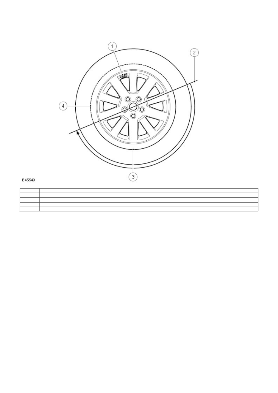
1
-
Tire valve and pressure sensor
2
-
Tire fitting/removal tool initial start position
3
-
High tire and bead tension area
4
-
Low tire and bead tension area
When removing the tire, the bead breaker must not be used within 90 degrees of the tire valve in each direction on each
side of the tire.
When using the tire removal machine, the fitting arm start position must be positioned as shown in the tire changing
illustration for each side of the tire. The wheel can then be rotated through 180 degrees in a counter-clockwise direction.
This will relieve tension from the tire bead allowing the remaining 180 degrees of the tire to be manually pulled from the
rim.
When refitting the tire, position the fitting arm as shown. Rotate the tire and take care that the bead on the low tension
side of the tire does not damage the sensor.
TREAD Act - NAS Only
Vehicles supplied to the North American markets must comply with the legislation of the Transport Recall Enhancement,
Accountability and Documentation (TREAD) act. Part of the requirement of the TREAD act is for the vehicle to display a
label, positioned on the driver's side 'B' pillar, which defines the recommended tire inflation pressure, load limits and
maximum load of passengers and luggage weight the vehicle can safely carry. This label will be specific to each individual
vehicle and will be installed on the production line.
This label must not be removed from the vehicle. The label information will only define the specification of the vehicle as
it came off the production line. It will not include dealer or owner fitted accessory wheels and tires of differing size from
the original fitment.
If the label is damaged or removed for body repair, it must be replaced with a new label specific to that vehicle. A new
label is requested from Land Rover parts and will be printed specifically for the supplied VIN of the vehicle.
TIRE PRESSURE MONITORING SYSTEM (TPMS)