Frelander 2. Manual - part 53
Stage 1:
Stage 2:
2.
WARNING: Make sure that a new lower arm ball
joint nut is installed.
CAUTION: Make sure that the ball joint ball does
not rotate.
Torque: 100 Nm
2.
3.
CAUTION: Do not allow halfshafts to hang unsupported at
one end or joint damage will occur.
Fully insert the front halfshaft into the wheel knuckle.
3.
4. NOTE: This step requires the aid of another technician.
Release the tension from the spring and damper assembly and
remove the special tool.
4.
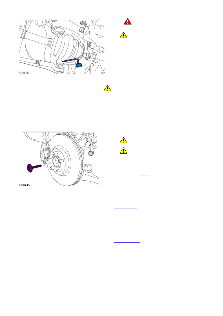
5. CAUTIONS:
Make sure that a new bolt is installed.
Make sure that the brake hose is not twisted and
is correctly located.
Install a new front halfshaft bolt.
Torque:
45 Nm
80°
5.
Install the wheel and tire.
Refer to:
Wheel and Tire
(204-04 W heels and Tires, Removal and
Installation).
6.
Lower the hood and secure the support struts with the clips.
7.
Install the plenum chamber panel.
Refer to:
Plenum Chamber
(412-01 Climate Control, Removal and
Installation).
8.