Frelander 2. Manual - part 52


  Index      Land Rover     Land Rover Frelander 2 - service repair manual 2006-2010 year


Search            


Content   ..  50  51  52  53   ..


Frelander 2. Manual - part 52


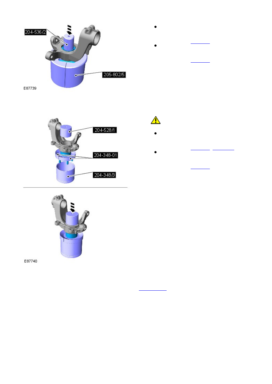
Position the wheel knuckle assembly in a press
and support on special tool.

Special Tool(s): 

205-802/5

Using the special tool, press the drive flange
assembly out of the wheel knuckle.

Special Tool(s): 

204-536/2

3.

Installation

1. 

CAUTION: Make sure that a new drive flange

assembly is installed.

Position the new drive flange assembly in the
special tools.

Special Tool(s): 

204-348/3

204-348-01

Using the special tool, press the drive flange
assembly into the wheel knuckle.

Special Tool(s): 

204-528/1

1.

Install the wheel knuckle.

Refer to: 

Wheel Knuckle

 (204-01 Front Suspension, Removal and

Installation).

2.

Front Suspension - Lower Arm

Removal and Installation

Special Tool(s)

204-619
G-Clamp

205-857
Remover, Halfshaft

211-316
Separator, Ball Joint

Removal

Remove the plenum chamber panel.

Refer to: 

Plenum Chamber

 (412-01 Climate Control, Removal and

Installation).

1.

Release the hood support struts and secure the hood in
an upright position.

2.

3. 

WARNING: Make sure to support the vehicle with axle

stands.

Raise and support the vehicle.

3.

Remove the wheel and tire.

Refer to: 

Wheel and Tire

 (204-04 W heels and Tires, Removal and

Installation).

4.

5. NOTE: This step requires the aid of another
technician.

Compress the spring and damper assembly.

Special Tool(s): 

204-619

5.

Remove and discard the front halfshaft bolt.

6.

Partially release the front halfshaft from the wheel
knuckle.

Special Tool(s): 

205-857

7.

8. 

CAUTION: Do not allow halfshafts to hang

unsupported at one end or joint damage will occur.

Partially release the front halfshaft from the wheel
knuckle.

8.

Stage 1:
Stage 2:

9. 

WARNING: Make sure that a new lower arm ball

joint nut is installed.

CAUTION: Make sure that the ball joint ball does

not rotate.

9.

Special Tool(s): 

211-316

10.

Remove and discard the lower arm bolts.

11.

Installation

1. NOTE: Make sure that new nuts and bolts are
installed.

Install the lower suspension arm.
Tighten bolt 1.

Torque:

140 Nm
45°

Tighten bolt 2 to

Torque: 175 Nm
Tighten bolt 3 to

Torque: 175 Nm

1.


Content   ..  50  51  52  53   ..