Freelander 1. Manual - part 64


  Index      Land Rover     Freelander 1 - service manual 2002 year


Search            


Content   ..  62  63  64  65   ..


Freelander 1. Manual - part 64


ENGINE - K SERIES 1.8

REPAIRS 12-2-29

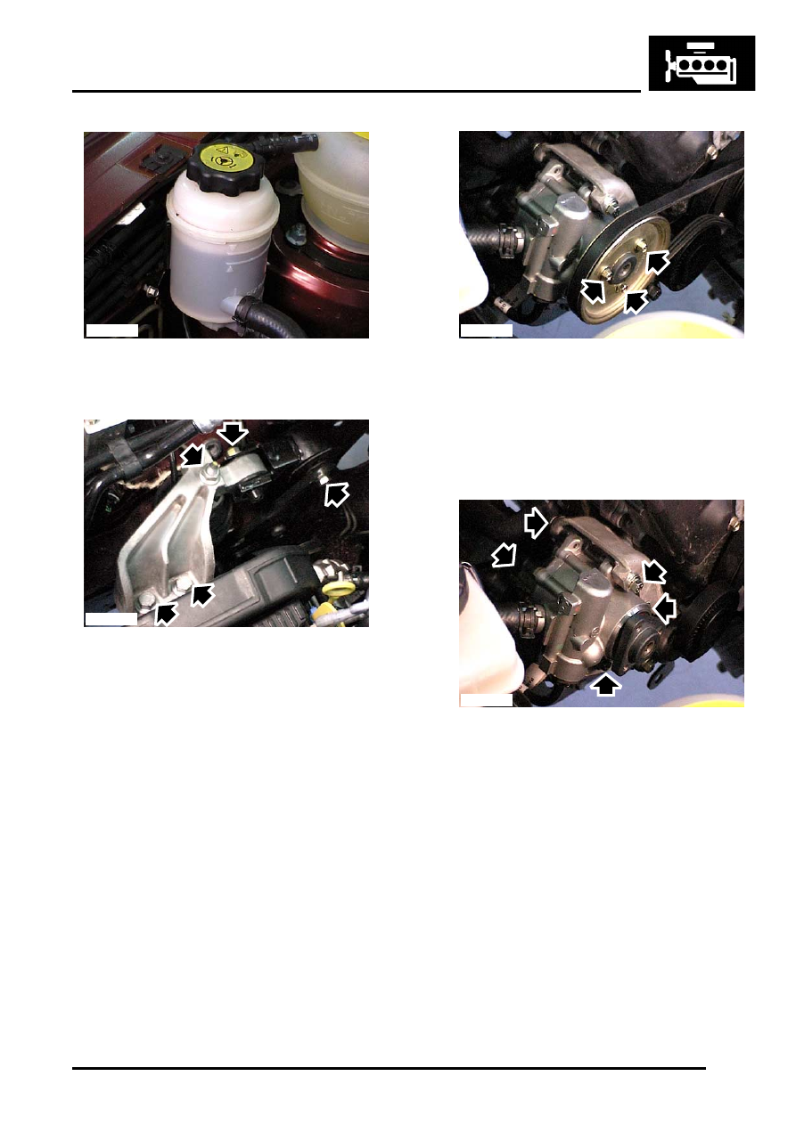
65. Release PAS reservoir from mounting bracket 

and position aside.

66. Remove bolt securing upper RH engine steady 

to top arm.

67. Loosen bolt securing upper RH engine steady 

to body, pivot engine steady away from top 
arm.

68. Remove nut securing top arm to RH 

hydramount, remove 2 bolts securing top arm 
to engine and remove top arm.

69. Raise engine and gearbox sufficient to gain 

access to PAS pump.

70. Loosen 3 PAS pump pulley bolts.
71. Using a 13 mm spanner, rotate PAS timing belt 

tensioner and insert a suitable 4 mm diameter 
pin through centre of hexagon into tensioner 
backplate. Remove PAS timing belt.

72. Remove 3 bolts securing PAS pump pulley and 

remove pulley.

73. Remove 5 bolts securing PAS pump to 

mounting bracket, release PAS pump and tie 
aside.

74. With assistance, manoeuvre and raise engine 

and gearbox from vehicle.

Refit

1. Connect hoist to adjustable lifting bracket, LRT-

12-138 on engine.

2. With assistance, manoeuvre and lower engine 

and gearbox into engine compartment 
sufficient to fit PAS pump.

3. Position PAS pump to mounting bracket, fit and 

tighten bolts to 25 Nm (18 lbf.ft).

4. Position pulley to PAS pump, fit and tighten 

bolts to 10 Nm (7.5 lbf.ft).

5. Position PAS timing belt to pulleys, relieve 

tensioner pressure, remove retaining pin and 
release tensioner.

M12 7161

M12 7162

M12 7163

M12 7164

ENGINE - K SERIES 1.8

12-2-30 REPAIRS

6. Lower engine and gearbox to position 

mountings.

7. Position mounting bracket to LH engine 

mounting, fit through bolt but do not tighten at 
this stage.

8. Align LH engine mounting bracket to body, fit 

and tighten bolts to 45 Nm (33 lbf.ft).

9. Tighten through bolt securing LH engine 

mounting to 80 Nm (59 lbf.ft).

10. Manoeuvre engine to position top arm.
11. Position top arm to RH hydramount and engine, 

fit bolts and tighten to 170 Nm (125 lbf.ft), fit nut 
and tighten to 85 Nm.

12. Lower hoist, disconnect and remove lifting 

bracket, LRT-12-138.

13. Position upper RH engine steady to top arm, fit 

and tighten bolt to 80 Nm (59 lbf.ft).

14. Tighten bolt securing upper RH engine steady 

to body to 80 Nm (59 lbf.ft).

15. Secure PAS fluid reservoir in mounting bracket.
16. Remove bolt securing engine lifting bracket, 

LRT-12-135/2 to front of cylinder head and 
remove bracket.

17. Remove 2 bolts securing engine lifting bracket, 

LRT-12-135/1 to rear of cylinder head and 
remove bracket.

18. Clean cover plate and mating face.
19. Position cover plate, fit bolts and tighten to 25 

Nm (18 lbf.ft).

20. Connect hose to underside of expansion tank 

and secure with clip. Secure hose in clip on 
body.

21. Connect expansion tank hose to inlet manifold 

and secure clip.

22. Connect top hose to coolant elbow and secure 

with clip.

23. Connect heater feed and return hoses and 

secure with clips.

24. Connect brake servo vacuum hose to inlet 

manifold.

25. Connect throttle inner cable to throttle cam and 

secure outer cable in abutment bracket.

26. Connect fuel feed hose to fuel rail.
27. Connect multiplug to purge control valve .
28. Position engine earth lead to body, fit and 

tighten nut to 9 Nm (7 lbf.ft).

29. Position battery lead to 'E' box mounting 

bracket and secure with clip.

30. Position battery and starter motor lead to 

underbonnet fuse box, fit and tighten bolts to 8 
Nm (6 lbf.ft).

31. Secure starter lead harness clips in 'E' box 

mounting bracket.

32. Connect multiplug to fusebox.
33. Fit engine compartment fuse box cover.
34. Position 'E' box, secure in retaining clip, fit and 

tighten nut to 9 Nm (7 lbf.ft).

35. Position carrier in 'E' box and secure with clips.

36. Position and secure air duct and harness 

rubber sleeve in 'E' box.

37. Connect engine harness multiplug in 'E' box.
38. Fit engine ECM.


 + 

 ENGINE MANAGEMENT SYSTEM - 

MEMS, REPAIRS, Engine control module 
(ECM) - combined ignition & fuel.

39. Raise vehicle on a ramp.
40. Models with A/C: Position A/C compressor to 

mounting bracket, fit and tighten bolts to 25 Nm 
(18 lbf.ft).

41. Models with A/C: Connect multiplug to A/C 

compressor.

42. Models with A/C: Position timing belt to 

compressor pulley, release tension, remove 
retaining pin and lower tensioner pulley onto 
timing belt

43. Position clutch slave cylinder mounting bracket 

to gearbox, fit and tighten bolts to 25 Nm (18 
lbf.ft).

44. Connect multiplug to 1st gear switch and 

secure harness with clip to clutch slave cylinder 
bracket.

45. Connect reverse light switch connectors.
46. Position lower engine steady to sump mounting 

bracket, fit and tighten bolt to 80 Nm (59 lbf.ft).

47. Tighten bolt securing lower engine steady to 

rear beam to 80 Nm (59 lbf.ft).

48. Position gear change steady rod, fit and tighten 

bolt to 25 Nm (18 lbf.ft).

49. Position gear change rod to selector shaft, fit 

NEW roll pin and secure cover.

50. Fit propeller shaft to IRD flange and align 

marks. Tighten nuts and bolts to 42 Nm (31 
lbf.ft).

51. Fit new gasket to exhaust manifold flange, 

connect exhaust front pipe and tighten nuts to 
75 Nm (55 lbf.ft).

52. Clean ends of drive shafts and mating splines 

in gearbox.

53. Fit drive shafts to IRD and gearbox, ensuring 

that the circlip on each driveshaft is fully 
engaged.

54. Locate lower arm bushes, fit but do not fully 

tighten bolts.

CAUTION: Nuts and bolts must be tightened 
with weight of vehicle on suspension.

55. Clean bush housing and mating faces on 

beam.

56. Align bush housings ensuring roll pin is 

correctly located. Fit bolts and tighten to 105 
Nm (77 lbf.ft).

57. Position LH and RH splash shields, fit and 

tighten bolts.

58. Lower vehicle.
59. Tighten lower arm front bush bolts to 175 Nm 

(129 lbf.ft).

ENGINE - K SERIES 1.8

REPAIRS 12-2-31

60. Tighten lower arm rear bush nuts to 140 Nm 

(103 lbf.ft).

61. Fit battery carrier.


 + 

 CHARGING AND STARTING, 

REPAIRS, Carrier - battery.

62. Adjust throttle cable.


 + 

 FUEL DELIVERY SYSTEM - 

PETROL, ADJUSTMENTS, Throttle cable - 
check and adjust - K1.8.

63. Fit air cleaner.


 + 

 FUEL DELIVERY SYSTEM - 

PETROL, REPAIRS, Air cleaner - K1.8.

64. If required, refill engine with oil. 


 + 

 MAINTENANCE, MAINTENANCE, 

Engine Oil and Filter – K1.8.

65. Fill IRD to correct level with fluid. 


 + 

 INTERMEDIATE REDUCTION 

DRIVE, ADJUSTMENTS, Intermediate 
reduction drive (IRD) fluid - drain & refill - 
Non NAS.

66. Refill gearbox with oil. 


 + 

 MANUAL GEARBOX - PG1, 

ADJUSTMENTS, Gearbox oil - drain and 
refill.

67. Refill cooling system


 + 

 COOLING SYSTEM - K SERIES 1.8, 

ADJUSTMENTS, Coolant - drain & refill.

68. Connect battery earth lead.
69. Fit bonnet.


 + 

 EXTERIOR FITTINGS, REPAIRS, 

Bonnet.

Arm assembly - engine mounting  RH 

$% 12.45.06

Remove

1. Remove underbelly panel.


 + 

 EXTERIOR FITTINGS, REPAIRS, 

Panel - underbelly.

2. Remove bolt securing upper RH engine steady 

to top arm.

3. Loosen bolt securing upper RH engine steady 

to body, pivot engine steady away from top 
arm.

4. Fit wooden block to jack, position jack under 

engine sump to support engine.

5. Remove nut securing engine top arm bracket to 

RH engine hydramount.

6. Remove 2 bolts securing top arm to engine 

front mounting bracket.

7. Remove top arm.

M12 7020

M12 7060

ENGINE - K SERIES 1.8

12-2-32 REPAIRS

Refit

1. Fit top arm.
2. Fit bolts securing top arm to engine front 

mounting bracket and tighten to 170 Nm (125 
lbf.ft).

3. Lower and remove jack supporting engine.
4. Fit nut securing top arm to RH hydramount and 

tighten to 85 Nm (63 lbf.ft).

5. Position upper RH engine steady to top arm, fit 

and tighten bolt to 80 Nm (59 lbf.ft).

6. Tighten bolt securing upper RH engine steady 

to body to 80 Nm (59 lbf.ft).

7. Fit underbelly panel.


 + 

 EXTERIOR FITTINGS, REPAIRS, 

Panel - underbelly.

Hydramount - engine - RH 

$% 12.45.12

Remove

1. Disconnect battery earth lead.
2. Remove engine RH mounting arm assembly.


 + 

 ENGINE - K SERIES 1.8, REPAIRS, 

Arm assembly - engine mounting RH.

3. Using LRT-12-169 loosen and remove 

hydramount.

Refit

1. Clean hydramount and body mating faces.
2. Fit hydramount.
3. Fit RH engine mounting arm assembly.


 + 

 ENGINE - K SERIES 1.8, REPAIRS, 

Arm assembly - engine mounting RH.

4. Connect battery earth lead.


Content   ..  62  63  64  65   ..