Freelander 1. Manual - part 46


  Index      Land Rover     Freelander 1 - service manual 2002 year


Search            


Content   ..  44  45  46  47   ..


Freelander 1. Manual - part 46


ENGINE - TD4

REPAIRS 12-1-27

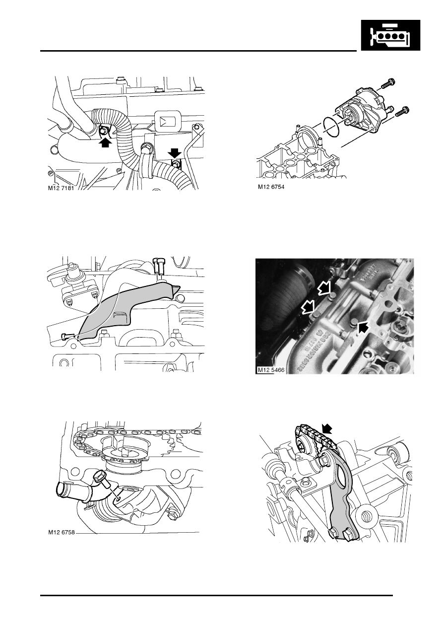
18. Remove bolt securing turbocharger outlet pipe 

to coolant rail.

19. Remove bolt securing turbocharger outlet pipe 

to bracket on exhaust manifold.

20. Remove 3 Allen screws heat shield to coolant 

rail.

21. Remove bolt, release coolant rail from 

thermostat housing and discard seal.

22. Remove heat shield.

23. Remove and discard 2 bolts securing vacuum 

pump.

24. Release vacuum pump and lay aside. Discard 

seal.

25. Remove 3 bolts securing turbocharger to 

exhaust manifold. Discard gasket.

26. Remove bolt securing PAS pipe clip to engine 

lifting eye.

M12 6785

M12 6759

ENGINE - TD4

12-1-28 REPAIRS

27. Remove 2 bolts and remove engine lifting eye.
28. Remove camshaft sprockets from timing chain.

29. Remove and discard timing chain guide 

support pins.

30. Remove chain guides. 

Access to remove guide from inlet side will 
improve when cylinder head is removed.

31. Remove 5 Allen screws and 1 cylinder head 

bolt securing cylinder head to timing cover.

32. Remove in sequence and discard 11 cylinder 

head bolts.

33. With assistance, remove cylinder head. 

Care must be taken to avoid damage to 
protruding glow plugs.

34. Identify thickness of cylinder head gasket by 

number of holes. Remove and discard gasket.

Refit

1. Clean mating faces of cylinder head and 

cylinder block, dowels and dowel holes. If 
necessary remove all traces of sealing 
compound with hard wood scraper. Ensure 
remnants do not remain in oil ways cooling 
ducts or bolt holes.

M12 6760

ENGINE - TD4

REPAIRS 12-1-29

2. Using a straight edge and feeler gauges, check 

cylinder head for distortion along lines shown in 
illustration
 

 + 

 GENERAL DATA, Engine – Td4 

Diesel.

3. Replace cylinder head if figures obtained 

exceed those given. Cylinder head must not be 
refaced.

4. Select replacement gasket which must have 

the same thickness/number of holes as the 
original unless new piston and connecting rod 
assemblies have been fitted. If new piston and 
connecting rod assemblies have been fitted, 
check piston protrusion to determine gasket 
thickness/number of holes required.
 

 + 

 ENGINE - Td4, ADJUSTMENTS, 

Piston protrusion - check - head removed.

5. Ensure sealing strips are intact on new cylinder 

head gasket and fit gasket to cylinder block.

6. Lightly oil 12 new cylinder head bolts.

7. With assistance, fit cylinder head and tighten 

11 cylinder head bolts in sequence to 80 Nm 
(59 lbf.ft). Ensure long bolt is fitted in position 
11 as shown. Loosen all bolts one half turn, 
then tighten all bolts to 50 Nm ( 37 lbf.ft). Use a 
suitable angle torque gauge and tighten all 
bolts in sequence by 90

°

 and then a final 90

°

.

8. Tighten remaining 41 mm long cylinder head 

bolt in position 12 to 110 Nm (81 lbf.ft).

9. Tighten Allen screws securing cylinder head to 

timing cover to 15 Nm (11 lbf.ft).

10. Clean timing chain guides.
11. Fit timing chain guides, Ensure guide on inlet 

side is located on its lower support pin and 
tighten both new upper support pins to 20 Nm 
(15 lbf.ft).

12. Clean camshaft sprockets.
13. Fit camshaft sprockets to timing chain.
14. Fit engine lifting eye and tighten bolts to 20 Nm 

(15 lbf.ft).

15. Tighten bolt securing PAS pipe clip to engine 

lifting eye to 10 Nm (7.5 lbf.ft).

16. Fit new gasket and tighten bolts securing 

turbocharger to exhaust manifold to 45 Nm (33 
lbf.ft).

17. Clean vacuum pump and mating face.
18. Fit new seal to vacuum pump, fit vacuum pump 

and tighten new bolts to 22 Nm (16 lbf.ft).

19. Clean coolant rail and thermostat housing 

mating face.

20. Fit heat shield.
21. Fit new seal to coolant rail, fit rail to thermostat 

housing and tighten bolt to 8 Nm (6 lbf.ft).

22. Tighten Allen screws securing heat shield to 8 

Nm.

23. Align EGR cooler and coolant rail, tighten bolts 

to 25 Nm (18 lbf.ft).

24. Fit EGR pipe clamp and tighten screw.
25. Align turbocharger outlet pipe and tighten 8 mm 

bolts to 25 Nm (18 lbf.ft)and 6 mm bolt to 10 Nm 
7.5 lbf.ft).

ENGINE - TD4

12-1-30 REPAIRS

26. Fit bolt securing fuel rails to support bracket 

and tighten to 10 Nm (7.5 lbf.ft).

27. Fit turbocharger outlet hose and tighten clips.
28. Connect expansion tank hose and secure with 

clip.

29. Clean coolant hose adaptor and mating face.
30. Fit new seal to hose adaptor, fit adaptor to 

cylinder head and tighten bolts to 8 Nm (6 lbf.ft).

31. Fit fuel rail and tighten Allen screws to 24 Nm ( 

18 lbf.ft).

32. Fit fuel pipe and support bush and tighten union 

nuts to 30 Nm (22 lbf.ft).

33. Connect multiplug to ECT sensor.
34. Connect glow plugs.
35. Connect multiplug to fuel pressure sensor.
36. Fit fuel pressure sensor harness grommet to 

cylinder head.

37. Fit tappets.


 + 

 ENGINE - Td4, REPAIRS, Tappets - 

head set.

38. Connect battery earth lead.
39. Refill cooling system.


 + 

 COOLING SYSTEM - Td4, 

ADJUSTMENTS, Coolant - drain and refill.

Tappets - head set 

$% 12.29.37

Remove

1. Disconnect battery earth lead.
2. Remove camshafts.


 + 

 ENGINE - Td4, REPAIRS, Camshaft 

- inlet or exhaust.

3. Remove rockers and retain in fitted order.

4. Remove tappets. Retain in fitted order if to be 

refitted.

CAUTION: Store hydraulic tappets in their 
fitted order and store inverted to prevent oil 
loss. Maintain absolute cleanliness when 
handling hydraulic tappets. Failure to 
observe these precautions can result in 
engine failure.


Content   ..  44  45  46  47   ..