Discovery 2. Manual - part 675
CHASSIS AND BODY DIMENSIONS
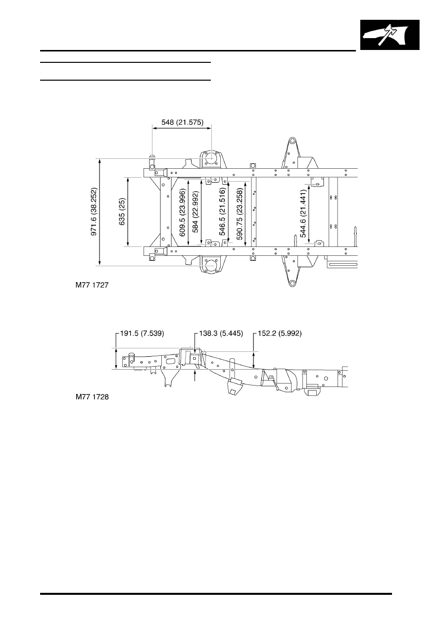
CHASSIS DIMENSIONS
77-1-3
Chassis dimensions - front end
Plan view
Side view
Figures shown outside brackets are metric measurements (millimetres) and those inside brackets are imperial
measurements (inches).