Discovery 2. Manual - part 599


  Index      Land Rover     Land Rover Discovery 2 - service manual 1999 year


Search            


Content   ..  597  598  599  600   ..


Discovery 2. Manual - part 599


STEERING

REPAIRS

57-45

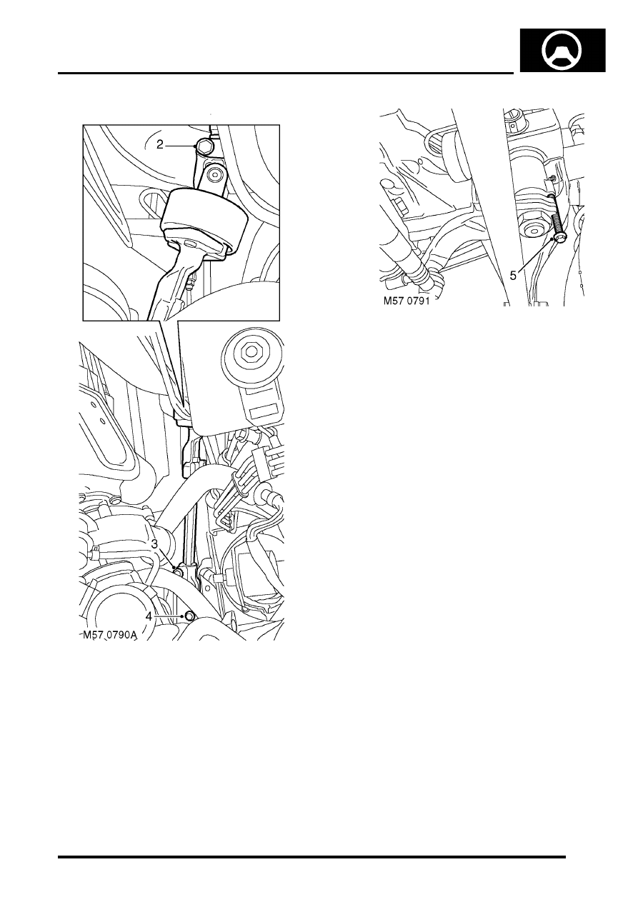
2. Remove bolt securing intermediate shaft  to 

steering column. 

3. Remove bolt securing intermediate  shaft to 

universal joint. 

4. Universal joint:  Remove the bolt securing the 

universal joint to the steering box.

5. Ensure steering wheel is in the straight  ahead 

position and fit centralising bolt to steering box. 
Remove the key from the ignition switch

CAUTION: Do not turn the steering wheel 
with the intermediate shaft or universal joint 
disconnected as damage to the rotary 
coupler and the steering wheel switches 
may occur.

STEERING

57-46

REPAIRS

6.  Intermediate shaft:  Slide the intermediate 

shaft upwards,  release from the universal joint 
and remove  intermediate shaft from the 
steering column. 

7.  Universal joint:  Slide the intermediate shaft 

upwards,  release from the universal joint and 
remove  universal joint from the steering box. 

Refit

1. Clean and inspect splines  for wear and 

damage. 

2. Intermediate shaft:  Locate intermediate shaft 

on steering  column and engage with universal 
joint. Ensure splines are fully engaged and  bolt 
holes aligned. 

3. Universal joint:  Locate universal joint on 

steering  box  and engage in intermediate shaft. 
Ensure splines are fully engaged and  bolt 
holes aligned. 

4. Fit bolts securing intermediate shaft to  

universal joint and tighten to 25 Nm (18 lbf.ft).  

5. Intermediate shaft: Fit bolts securing 

intermediate shaft to steering column  and 
tighten to 25 Nm (18 lbf.ft).  

6. Universal joint: Fit bolts securing universal 

joint to steering box and tighten to 25 Nm (18 
lbf.ft).  

7. LHD diesel:  Connect hose to turbocharger 

and intercooler and secure the clips.

8. Fit ignition key, remove steering box 

centralising bolt  and check that steering wheel 
is in the straight  ahead position. 

STEERING

REPAIRS

57-47

Nacelle - steering column

$% 57.40.29

Remove

1. Open fascia lower access panel.

2. Remove 3 screws securing steering column 

nacelle halves together.

3. Release clips securing nacelle together and 

remove from steering column.

Refit

1. Position nacelle to steering column and secure 

with clips and screws.

2. Close fascia lower access panel.

Drop arm - steering box  

$% 57.50.14 

Remove

1. Remove steering box.

l

For V8 models: 
 

 STEERING, REPAIRS, Power 

steering box - V8.

l

For LHD diesel models: 
 

 STEERING, REPAIRS, Power 

steering box - LHD - diesel.

l

For RHD diesel models
 

 STEERING, REPAIRS, Steering 

box - RHD - diesel.

2. Secure steering box in vice. 
3. Release drop arm nut lock washer. 
4. Loosen but do not remove nut securing drop 

arm. 

5. Using LRT-57-012 release drop  arm. 
6. Remove nut and lock washer. 
7. Remove drop arm. 

Refit

1. Clean drop arm and steering box splines. 
2. Ensure steering box is in the central position. 

Align and fit drop arm to output shaft and 
secure with lock washer and nut. Tighten nut to 
240 Nm  (177 lbf.ft).

3. Secure lock washer to drop arm nut.
4. Fit steering box.

l

For V8 models: 
 

 STEERING, REPAIRS, Power 

steering box - V8.

l

For LHD diesel models: 
 

 STEERING, REPAIRS, Power 

steering box - LHD - diesel.

l

For RHD diesel models
 

 STEERING, REPAIRS, Steering 

box - RHD - diesel.

STEERING

57-48

REPAIRS

Ball joint - track rod  

$% 57.55.07 

Remove

1. Raise front of vehicle. 

WARNING: Do not work on or under a 
vehicle supported only by a jack. Always 
support the vehicle on safety stands.

2. Remove LH front road wheel. 

3. Loosen adjuster clamp bolts. 
4. Remove nut securing track rod ball  joint to 

steering knuckle. 

5. Using tool LRT-57-036 break taper  joint and 

release track rod. 

CAUTION: Before disconnecting any part of 
the steering linkage, ensure the road wheels 
are positioned straight ahead and the 
steering wheel is prevented from turning. 
Unrestricted turning of the steering wheel 
will damage the SRS rotary coupler.

6. Unscrew ball joint and adjuster. 
7. Remove clamps from adjuster and track rod. 

Refit

1. Clean adjuster, clamps and track rod. 
2. Fit clamps to track rod and adjuster. Screw in 

adjuster and ball joint. 

3. Clean ball joint taper and taper seat. 
4. Adjust length of track rod so that ball joint taper 

is centralised in steering knuckle.

5. Fit track rod to steering knuckle and tighten nut 

to 80 Nm (59 lbf.in).

6. Fit road wheel and tighten nuts to 140 Nm (103 

lbf.ft).

7. Remove stand(s) and lower vehicle.
8. Check and, if necessary, adjust wheel 

alignment
 

 STEERING, ADJUSTMENTS, Wheel 

alignment - front.

9. After check/adjustment of wheel alignment, 

ensure track rod adjuster clamp bolts are 
tightened. Tighten M8 bolts to 22 Nm (16 lbf.ft) 
and M10 bolts to 33 Nm (24 lbf.ft).


Content   ..  597  598  599  600   ..