Discovery 2. Manual - part 581


  Index      Land Rover     Land Rover Discovery 2 - service manual 1999 year


Search            


Content   ..  579  580  581  582   ..


Discovery 2. Manual - part 581


REAR AXLE

DESCRIPTION AND OPERATION

51-1

REAR AXLE

DESCRIPTION AND OPERATION

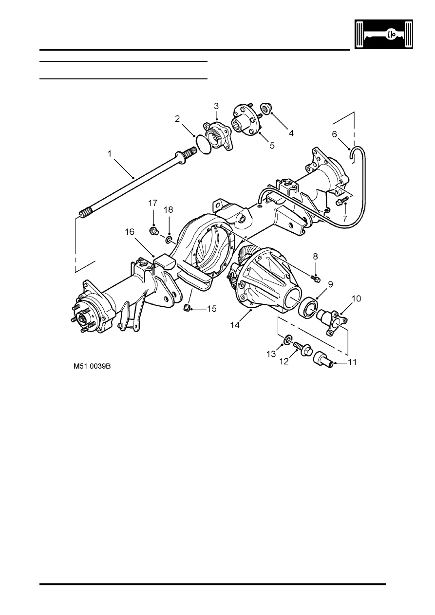
Rear axle component layout

Drive shaft
'O' ring
Hub bearing
Stake nut
Hub flange
Breather tube
Bolt
Bolt
Oil seal

10 Pinion flange
11 Centralising peg
12 Bolt
13 Washer
14 Differential unit
15 Drain plug
16 Axle casing
17 Oil level plug
18 'O' ring

REAR AXLE

51-2

DESCRIPTION AND OPERATION

Description

General
The rear axle consists of an axle casing with a differential unit attached to the right of the vehicle centre line. A wheel 
hub is installed in each end of the axle casing and connected to the differential unit by a drive shaft.

Axle casing
The axle casing is of welded construction, with brackets on the casing exterior for attachment to the rear suspension.

A differential cover on the rear of the axle casing contains an oil level plug for checking and replenishment of the 
differential unit lubricating oil. A magnetic drain plug is installed on the underside of the axle casing.

The interior of the axle casing is ventilated through a breather tube inserted in a red plastic sleeve in the top of the 
casing. The open end of the breather tube is located between the chassis and the left rear wheelarch.

Differential unit
The differential unit is of the spiral bevel type, lubricated by splash oil. The unit consists of a differential carrier 
attached to a pinion housing. In the pinion housing, the pinion is splined to a pinion flange which is secured with a bolt 
and washer. An oil seal prevents leakage past the pinion flange.

Centralising peg
The centralising peg is a press fit in the centre of the pinion flange and provides a positive location for the rear 
propellor shaft to ensure it is centralised with the  flange.

REAR AXLE

DESCRIPTION AND OPERATION

51-3

Wheel hub

Section through wheel hub

'O' ring
Hub bearing
Hub flange
Wheel stud

Stake nut
ABS sensor ring
Drive shaft
Axle casing

Each wheel hub consists of a hub flange pressed into a hub bearing.

The hub flange is splined to accept the outboard end of the drive shaft, which is secured to the hub flange with a stake 
nut. Five studs are installed in the hub flange for the wheel nuts, and a threaded hole is provided for the brake disc 
securing screw.

The outer race of the hub bearing is bolted to the end of the axle casing. An 'O' ring seals the joint between the outer 
race and the axle casing to prevent leakage of differential lubricating oil. The hub bearing is a sealed unit which 
contains twin opposed roller bearings, pre-packed with grease during manufacture. A toothed ABS sensor ring is 
integrated into the inner race of the hub bearing. An opening in the outer race of the hub bearing accommodates the 
ABS sensor.

Drive shaft
Each drive shaft consists of a solid rod, splined at both ends.

REAR AXLE

51-4

DESCRIPTION AND OPERATION


Content   ..  579  580  581  582   ..