Discovery 2. Manual - part 556


  Index      Land Rover     Land Rover Discovery 2 - service manual 1999 year


Search            


Content   ..  554  555  556  557   ..


Discovery 2. Manual - part 556


TRANSFER BOX - LT230SE

REPAIRS

41-27

Transfer box - V8

$% 41.20.25.99 

Remove

1. Remove front exhaust pipe.


 + 

 MANIFOLDS AND EXHAUST 

SYSTEMS - V8, REPAIRS, Front pipe.

2. Drain transfer box oil. 


 + 

 MAINTENANCE, PROCEDURES, 

Transfer box.

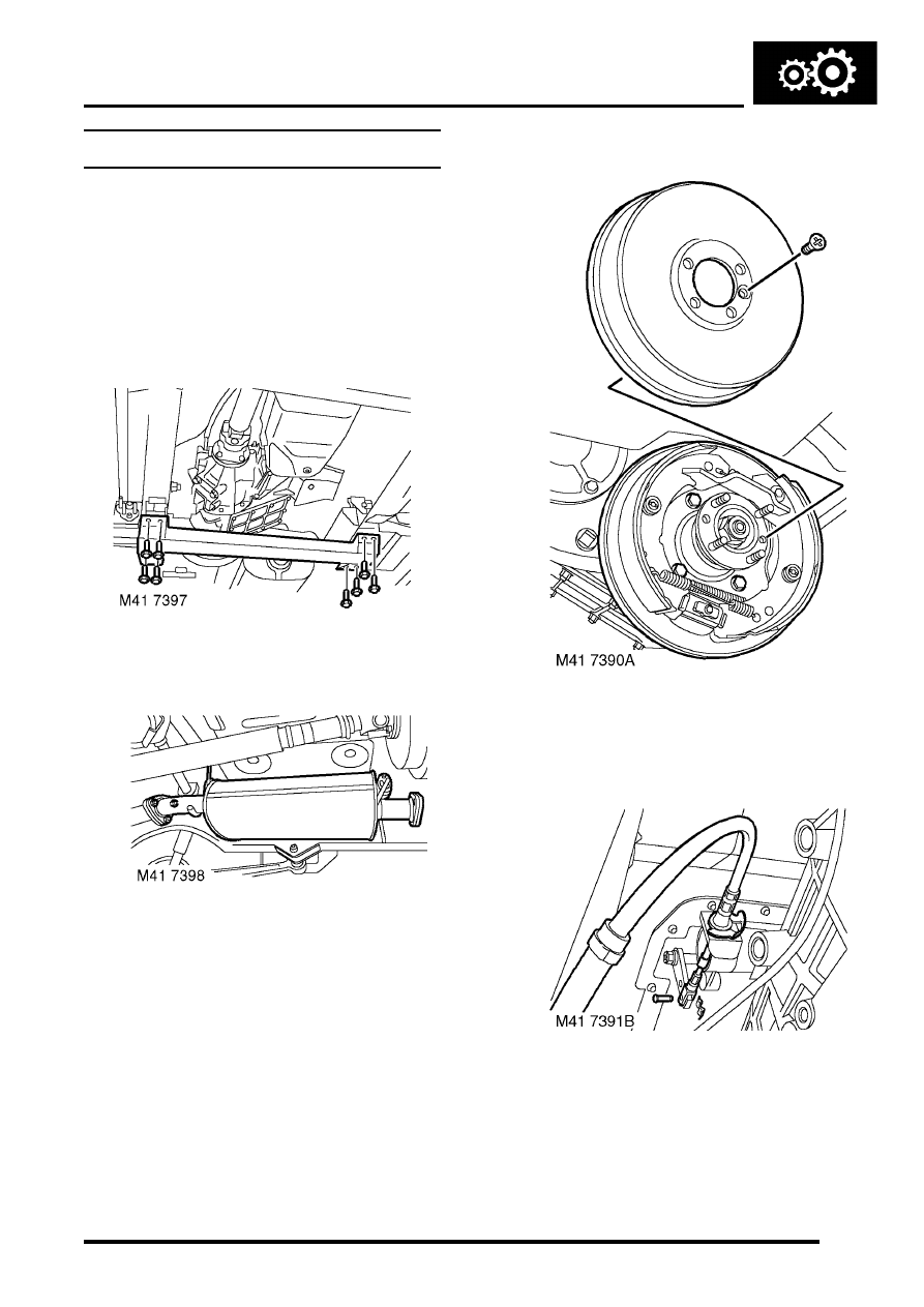
3. Remove 8 bolts securing rear cross  member 

and remove cross member. 

4. Remove 3 nuts securing intermediate  silencer 

to tail pipe. 

5. Release silencer from mounting rubbers,  

remove silencer and discard gasket. 

6. Remove front propeller shaft. 


 + 

 PROPELLER SHAFTS, REPAIRS, 

Propeller shaft - front.

7. Remove rear propeller shaft. 


 + 

 PROPELLER SHAFTS, REPAIRS, 

Propeller shaft - rear.

8. Remove handbrake drum retaining screw and 

remove handbrake drum. 

9. Remove 4 bolts from handbrake back plate, 

release back plate and tie aside. 

10. Remove clevis pin and 'C' washer securing 

high/low ratio selector cable  to selector lever 
and release cable from abutment bracket.  

TRANSFER BOX - LT230SE

41-28

REPAIRS

11. Remove 2 cable ties securing cable to  fuel 

pipes. 

12. Disconnect 2 Lucars from oil temperature  

sensor and disconnect reverse lamp switch  
multiplug. 

13. Remove banjo bolt securing breather pipe  and 

discard washers. 

14.  If fitted -  Disconnect 2 Lucars from differential 

lock switch. 

15. Release and disconnect transfer box neutral 

switch  multiplug. 

16. Remove 4 bolts from transfer box bottom plate, 

position support plate   LRT-99-010  to transfer 
box and tighten bolts. 

17. Position gearbox support jack and  secure 

support plate to jack using 4 bolts. 

18. Remove 3 bolts securing transfer box to 

gearbox.

19. Fit 3 guide studs   LRT-41-009  through transfer 

box bolt holes to support it  during removal. 

20. Remove 2 bolts and nut securing transfer box 

to gearbox case.  If  securing stud is removed 
during this operation, it must be discarded  
and a new stud fitted.
  

21. Position a jack to support gearbox  and engine. 

TRANSFER BOX - LT230SE

REPAIRS

41-29

22. Remove 4 bolts and nut securing RH  mounting 

to body and transfer box. 

23. Remove nut securing LH mounting to body. 
24. Raise gearbox and remove RH mounting. 
25. With assistance, remove transfer box from 

gearbox. 

26. Remove input shaft oil seal.


 + 

 TRANSFER BOX - LT230SE, 

REPAIRS, Oil seal - input shaft.

Refit

1. Fit new input shaft oil seal.


 + 

 TRANSFER BOX - LT230SE, 

REPAIRS, Oil seal - input shaft.

2. Clean transfer box to gearbox  mating faces. 
3. Raise transfer box on jack and align to guide 

studs   LRT-41-009

4. Clean transfer box to gearbox bolt threads. 
5. Apply Loctite 290 to bolt and stud threads. 
6. Fit and lightly tighten 2 bolts and nut securing 

transfer box to  gearbox.  If  new stud is to be 
fitted apply Loctite 290 to threads of stud 
and tighten to 45 Nm (33 lbf.ft) 

7. Remove guide studs, fit and lightly tighten 3 

bolts.

8. Tighten  bolts and nut by diagonal selection to 

45 Nm  (33 lbf.ft.

9. Position  gearbox RH mounting and  tighten 

bolts to 85 Nm (63 lbf.ft). 

10. Tighten  gearbox RH mounting nut  to 48 Nm 

(35 lbf.ft).  

11. Fit nut to LH mounting and tighten  to 48 Nm (35 

lbf.ft). 

12. Remove 4 bolts securing support plate to  

gearbox jack. 

13. Remove 4 bolts securing support plate LRT-99-

010  to transfer box and remove plate. 

14. Clean threads of bottom plate bolts.
15. Apply Loctite 290 to threads of bolts.
16. Fit  4 bolts securing bottom plate and tighten to 

25 Nm  (18 lbf.ft). 

17. Using new washers position breather pipe and 

tighten banjo bolt. 

18. Connect multiplug to transfer box neutral switch 

and secure harness. 

19.  If fitted -  Connect Lucars to differential  lock 

switch.

20. Connect multiplug and Lucars to reverse lamp 

switch and oil temperature sensor. 

21. Position high/low ratio selector cable and 

secure with 'C' washer  and clevis pin. 

22. Secure cable to fuel pipes with new  cable ties. 
23. Clean handbrake back plate and mating face. 
24. Position  handbrake back plate, fit bolts and 

tighten to 75 Nm (55 lbf.ft).  

25. Clean handbrake drum. 
26. Fit handbrake drum and tighten retaining 

screw. 

27. Fit  front propeller shaft. 


 PROPELLER SHAFTS, REPAIRS, 

Propeller shaft - front.

28. Fit rear propeller shaft. 


 + 

 PROPELLER SHAFTS, REPAIRS, 

Propeller shaft - rear.

29. Clean exhaust silencer and tail pipe  mating 

faces. 

30. Position silencer and secure on  mountings, 

using a new gasket align to tail  pipe, fit nuts 
and tighten to 25 Nm  (18 lbf.ft). 

31. Position rear cross member,  fit  bolts and 

tighten to 26 Nm (19 lbf.ft). 

32. Refill transfer box with oil. 


 + 

 MAINTENANCE, PROCEDURES, 

Transfer box. 

33. Fit front exhaust pipe.


 + 

 MANIFOLDS AND EXHAUST 

SYSTEMS - V8, REPAIRS, Front pipe.

TRANSFER BOX - LT230SE

41-30

REPAIRS

Gasket - rear cover plate

$% 41.20.30 

Remove

1. Mark rear cover to bearing housing for 

assembly purposes. 

2. Note fitted position of stud nut, remove  stud nut 

and 5 bolts securing rear cover. 

3. Carefully release rear cover from  bearing 

housing. 

Refit

1. Clean rear cover, mating face on bearing  

housing and sealant from stud/bolt threads. 

2. Apply sealant Part No. STC 3254 to rear cover  

mating face. 

3. Align reference marks and position rear  cover. 
4. Apply Loctite 290 to stud/bolt threads,  fit rear 

cover plate stud nut and bolts and tighten to  25 
Nm (18 lbf.ft). 

5. Top-up transfer box oil. 


 + 

 MAINTENANCE, PROCEDURES, 

Transfer box.

Switch - differential lock - Up to 03 MY

$% 41.20.34

Remove

1. Remove front propeller shaft.


 PROPELLER SHAFTS, REPAIRS, 

Propeller shaft - front.

2. Disconnect 2 Lucars from  switch.
3. Remove switch and remove nut from switch.

Refit

1. Clean switch and gearbox face.

2. Fit nut to switch with counterbore positioned 

towards switch head. The nut acts as a spacer 
to ensure that switch setting is correct. 
Always ensure that nut is fully tightened to 
switch head, (no gap)
.

3. Apply Hylomar PL 32 sealant to switch thread.
4. Position switch into front output housing until 

nut bottoms out on housing.   


Content   ..  554  555  556  557   ..