Discovery 2. Manual - part 482
ENGINE MANAGEMENT SYSTEM - V8
DESCRIPTION AND OPERATION
18-2-7
The ECM controls the following outputs:
l
Fuel injectors (1 per cylinder).
l
Ignition coils/ high tension leads/ spark plugs.
l
Fuel pump relay.
l
Idle air control valve.
l
Heated oxygen sensors.
l
EVAP canister purge valve.
l
EVAP canister vent solenoid (CVS) valve (where fitted).
l
Malfunction Indicator Lamp (MIL)/ service engine soon lamp (where fitted).
l
Hill descent control (via SLABS interface).
l
EVAP system fuel leak detection pump (where fitted)
l
Secondary air injection pump (where fitted)
The ECM also interfaces with the following:
l
Diagnostics via diagnostic connector with TestBook.
l
Controller Area Network (CAN) link to EAT ECU.
l
Air conditioning system.
l
Self Levelling & Anti-lock Braking System (SLABS) ECU.
l
Immobilisation system via the body control unit (BCU).
l
Instrument cluster.
l
Cruise control ECU
l
Active Cornering Enhancement (ACE) ECU
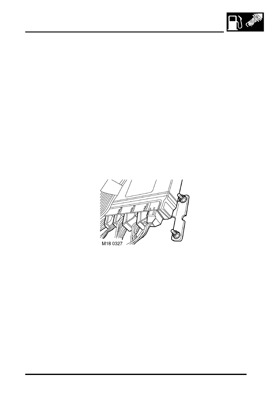
Engine Control Module (ECM)
The engine control module (ECM) is located on the RH side A post below the face panel inside the vehicle. It has a
cast aluminium case and is mounted on a bracket. The ECM has 5 independent connectors totalling 134 pins.
The ECM is available in 4 variants:
l
NAS.
l
NAS low emission vehicles.
l
UK/ Europe/ Japan/ Australia.
l
ROW/ Gulf.
The ECM uses a 'flash' electronic erasable programmable read only memory (EEPROM). This enables the ECM to
be externally configured, to ensure that the ECM can be updated with any new information, this also allows the ECM
to be configured with market specific data. TestBook must be used to configure replacement ECM's. The ECM can
be reconfigured up to 16 times to meet changing specifications and legislation.
The ECM memorises the positions of the crankshaft and the camshaft when the engine has stopped via the CKP and
CMP sensors. This allows immediate sequential fuel injection and ignition timing during cranking. This information is
lost if battery voltage is too low (i.e. flat battery). So the facility will be disabled for the first engine start.