Discovery 2. Manual - part 481


  Index      Land Rover     Land Rover Discovery 2 - service manual 1999 year


Search            


Content   ..  479  480  481  482   ..


Discovery 2. Manual - part 481


ENGINE MANAGEMENT SYSTEM - V8

DESCRIPTION AND OPERATION

18-2-3

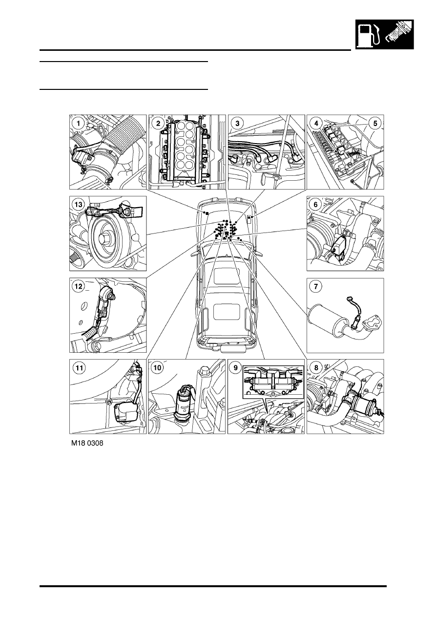
Engine management component 
location - Engine compartment

Mass air flow/ inlet air temperature sensor 
Fuel injectors
High tension leads/spark plugs
Fuel pump relay 
ATC compressor clutch relay/ cooling fan relay
Throttle position sensor 
Heated oxygen sensor
Idle air control valve
Ignition coils

10 Engine coolant temperature sensor
11 Crankshaft speed and position sensor
12 Knock sensor
13 Camshaft position sensor

ENGINE MANAGEMENT SYSTEM - V8

18-2-4

DESCRIPTION AND OPERATION

Engine management block diagram

ENGINE MANAGEMENT SYSTEM - V8

DESCRIPTION AND OPERATION

18-2-5

Engine control module
Crankshaft speed and position sensor
Camshaft position sensor
Engine coolant temperature sensor
Mass air flow/ inlet air temperature sensor 
Throttle position sensor 
Heated oxygen sensors
Fuel injectors
Idle air control valve

10 Fuel pump relay
11 EVAP canister
12 EVAP canister vent valve
13 EVAP canister purge valve 
14 Fuel tank pressure sensor
15 Ignition coils
16 Knock sensor
17 Spark plugs
18 High/ Low ratio switch
19 Malfunction indication lamp
20 Diagnostic connector
21 Air temperature control clutch relay
22 Air temperature control cooling fan relay
23 ATC ECU
24 CAN link to EAT
25 SLABS ECU
26 BCU
27 Instrument cluster
28 Thermostat monitoring sensor (where fitted)

ENGINE MANAGEMENT SYSTEM - V8

18-2-6

DESCRIPTION AND OPERATION

Description - engine management

General
The V8 engine is equipped with the Bosch Motronic M5.2.1 engine management system. This system is a sequential 
multiport fuel injection system controlled by an Engine Control Module (ECM). 

A single ECM is used for the control of the existing 4.0 litre engine and the new 4.6 litre engine introduced with 03 
model year vehicles for the NAS market only. The ECM contains the tunes for both engines variants. When the ECM 
is replaced, TestBook/T4 must be used to select the correct tune to match the engine fitment.

The ECM has On Board Diagnostic (OBD) strategies as required by various market legislative bodies. To meet these 
requirements the system monitors and reports on any  faults that cause excessive exhaust emissions. 

In markets that mandate OBD, the ECM monitors performance of the engine for misfires, catalyst efficiency, exhaust 
leaks and evaporative control loss. If a fault occurs, the ECM stores the relevant fault code and warns the driver of 
component failure by illuminating the Malfunction Indicator Light in the instrument pack.

In markets where OBD is not mandatory, the ECM will still monitor performance of the engine and store the fault code, 
but will not  illuminate the Malfunction Indicator Light.

The ECM uses input and output information from its sensors and actuators to control the following engine conditions:

l

Fuel quantity.

l

Closed loop fuelling.

l

Open loop fuelling.

l

Ignition timing.

l

Knock control.

l

Idle speed control.

l

Emission control.

l

On-Board Diagnostic (OBD) where applicable.

l

Vehicle immobilisation.

l

Misfire detection (where applicable).

l

Vehicle speed signal.

l

Rough road signal (where applicable).

l

Low fuel level signal (where applicable).

l

Coolant temperature gauge signal.

The ECM processes sensor information from the following input sources:

l

Ignition switch (position II).

l

Crankshaft speed and position sensor.

l

Camshaft position sensor.

l

Engine coolant temperature sensor.

l

Mass air flow sensor.

l

Intake air temperature sensor.

l

Knock sensor.

l

Throttle position sensor.

l

Heated oxygen sensors.

l

High/ Low ratio switch.

l

Fuel tank pressure sensor (where fitted)

l

Thermostat monitoring sensor (where fitted)


Content   ..  479  480  481  482   ..