Discovery 2. Manual - part 457


  Index      Land Rover     Land Rover Discovery 2 - service manual 1999 year


Search            


Content   ..  455  456  457  458   ..


Discovery 2. Manual - part 457


EMISSION CONTROL - V8

DESCRIPTION AND OPERATION 17-2-27

The ECM connector and pins pertinent for secondary air injection are listed in the following table:

Secondary air injection system components
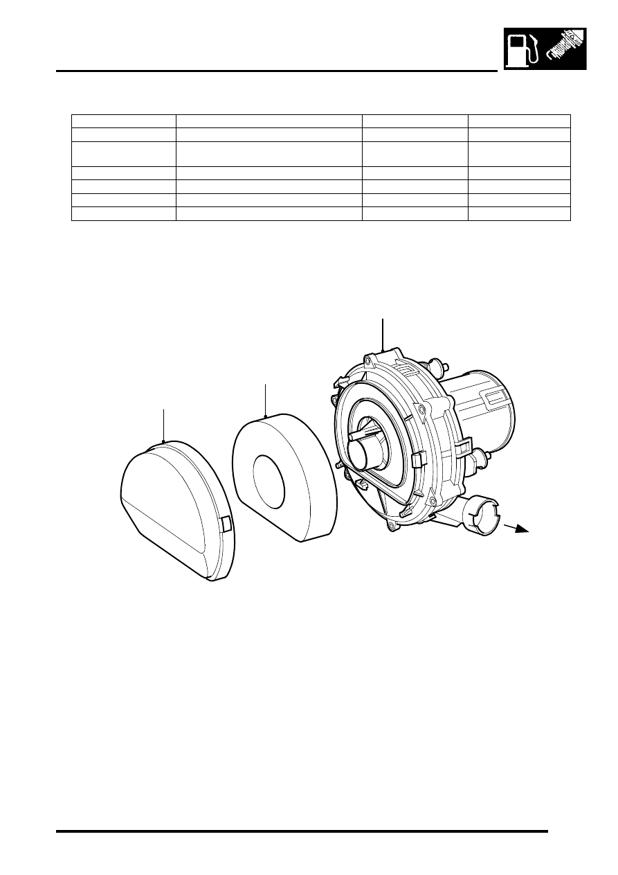
The secondary air injection (SAI) system components (NAS only) are described below:

Secondary air injection (SAI) pump

SAI pump cover
Foam filter
SAI pump
Pressurised air to exhaust manifolds

Connector / Pin No.

Description

Signal type

Control

C0635-23

Main relay output

Output drive

Switch to ground

C0636-4

Secondary air injection vacuum solenoid 
valve control

Output, drive

Switch to ground

C0636-16

Secondary air injection pump relay control

Output drive

Switch to ground

C0636-21

Coolant temperature (ECT) sensor

Ground

0V

C0636-22

Coolant temperature (ECT) sensor

Input signal

Analogue 0 - 5V

C0637-20

MIL "ON"

Output drive

Switch to ground

M17 0204

1

4

2

3

EMISSION CONTROL - V8

17-2-28 DESCRIPTION AND OPERATION

The SAI pump is attached to a bracket at the rear RH side of the engine compartment and is fixed to the bracket by 
three studs and nuts. The pump is electrically powered from a 12V battery supply via a dedicated relay and supplies 
approximately 35kg/hr of air when the vehicle is at idle in Neutral/Park on a start from 20

°

C (68

°

F).

Air is drawn into the pump through vents in its front cover and is then passed through a foam filter to remove 
particulates before air injection. The air is delivered to the exhaust manifold on each side of the engine through a 
combination of plastic and metal pipes.

The air delivery pipe is a flexible plastic type, and is connected to the air pump outlet via a plastic quick-fit connector. 
The other end of the flexible plastic pipe connects to the fixed metal pipework via a short rubber hose.  The part of the 
flexible plastic pipe which is most vulnerable to engine generated heat is protected by heat reflective sleeving.  The 
metal delivery pipe has a fabricated T-piece included where the pressurised air is split for delivery to each exhaust 
manifold via the SAI control valves.

The pipes from the T-piece to each of the SAI control valves are approximately the same length, so that the pressure 
and mass of the air delivered to each bank will be equal. The ends of the pipes are connected to the inlet port of each 
SAI control valve through short rubber hose connections.

The T-piece is mounted at the rear of the engine (by the ignition coils) and features a welded mounting bracket which 
is fixed to the engine by two studs and nuts.

The foam filter in the air intake of the SAI pump provides noise reduction and protects the pump from damage due to 
particulate contamination. In addition, the pump is fitted on rubber mountings to help prevent noise which is generated 
by pump operation from being transmitted through the vehicle body into the passenger compartment.

If the secondary air injection pump malfunctions, the following fault codes may be stored in the ECM diagnostic 
memory, which can be retrieved using 'Testbook':

Secondary air injection (SAI) pump relay
The secondary air injection pump relay is located in the engine compartment fusebox. The engine control module 
(ECM) is used to control the operation of the SAI pump via the SAI pump relay. Power to the coil of the relay is supplied 
from the vehicle battery via the main relay and the ground connection to the coil is via the ECM.

Power to the SAI pump relay contacts is via fusible link FL2 which is located in the engine compartment fusebox.

P-code

Description

P0418

Secondary air injection pump powerstage fault (e.g. - SAI pump relay fault / SAI 
pump or relay not connected / open circuit / harness damage).

EMISSION CONTROL - V8

DESCRIPTION AND OPERATION 17-2-29

Secondary air injection (SAI) vacuum solenoid valve

Vacuum port to intake manifold (via vacuum 

reservoir)

SAI vacuum solenoid valve
Electrical connector
Vacuum port to vacuum operated SAI control 

valves

Purge valve clip
Mounting bracket

The SAI vacuum solenoid valve is located at the rear LH side of the engine and is electrically operated under the 
control of the ECM. The SAI vacuum solenoid valve is mounted on a bracket together with the EVAP system purge 
valve.

Vacuum to the SAI vacuum solenoid valve is provided from the intake manifold depression via a vacuum reservoir. A 
small bore vacuum hose with rubber elbow connections at each end provides the vacuum route between the vacuum 
reservoir and SAI vacuum solenoid valve.  A further small bore vacuum hose with a larger size elbow connector is 
used to connect the SAI vacuum solenoid valve to the SAI control valves on each side of the engine via an 
intermediate connection.  The SAI vacuum solenoid valve port to the SAI control valves is located at a right angle to 
the port to the vacuum reservoir.  

The intermediate connection in the vacuum supply line is used to split the vacuum equally between the two SAI control 
valves. The vacuum hose intermediate connection is located midpoint in front of the inlet manifold. All vacuum hose 
lines are protected by flexible plastic sleeving.

M17 0211

1

4

2

3

5

6

EMISSION CONTROL - V8

17-2-30 DESCRIPTION AND OPERATION

Electrical connection to the SAI vacuum solenoid valve is via a 2–pin connector. A 12V electrical power supply to the 
SAI vacuum solenoid valve is provided via the Main relay and Fuse 2 in the engine compartment fusebox. The ground 
connection is via the ECM which controls the SAI vacuum solenoid valve operation. Note that the harness 
connector to the SAI solenoid valve is grey, and must not be confused with the harness connector to the 
EVAP system purge valve which is black.

The ECM switches on the SAI vacuum solenoid valve at the same time as initiating SAI pump operation. When the 
SAI vacuum solenoid valve is open, a steady vacuum supply is allowed through to open the two vacuum operated 
SAI control valves. When the ECM breaks the earth path to the SAI vacuum solenoid valve, the valve closes and 
immediately shuts off the vacuum supply to the two SAI control valves at the same time as the SAI pump operation 
is terminated.

If the SAI vacuum solenoid valve malfunctions, the following fault codes may be stored in the ECM diagnostic 
memory, which can be retrieved using 'Testbook':

SAI control valves

Pressurised air from SAI pump
Vacuum operated SAI control valve
Vacuum hose from SAI vacuum solenoid valve

Pressurised air to exhaust manifold
Protective heat sleeving
Air delivery pipe to exhaust manifold

P-code

Description

P0413

SAI vacuum solenoid valve not connected, open circuit

P0414

SAI vacuum solenoid valve short circuit to ground

P0412

SAI vacuum solenoid valve powerstage fault - harness damage, short circuit to 
battery supply voltage

M17 0205

1

3

4

4

2

6

5


Content   ..  455  456  457  458   ..