Discovery 2. Manual - part 295
AIR CONDITIONING
DESCRIPTION AND OPERATION
82-19
Diagnostics
The ATC ECU performs a diagnostic check each time the ignition is switched on. To avoid nuisance fault indications
at low light levels, the sunlight sensor is omitted from the diagnostic check. If a fault is detected, the audible warning
sounds three times and the AUTO window on the control panel display flashes for 20 seconds. The ATC ECU then
reverts to normal control but uses a default value or strategy for the detected fault. Faults are identified by performing
a manual diagnostic check of the system.
A manual diagnostic check includes a check of the sunlight sensor, and is initiated by pressing and holding the AUTO
switch and the air distribution switch, then turning the ignition switch from off to on. The audible warning sounds once
and the indications on the control panel display illuminate. FC is shown in the LH temperature window and the results
of the check are shown as a two digit fault code in the RH temperature window. If a fault is detected, the audible
warning sounds three times and the AUTO window on the display flashes on and off for 20 seconds. If more than one
fault is detected, the fault codes cycle in numerical order, at 1 Hz. The audible warning sounds as each fault code is
shown. In low light conditions, to avoid false sunlight sensor fault indications, the sunlight sensor should be illuminated
with a strong light source.
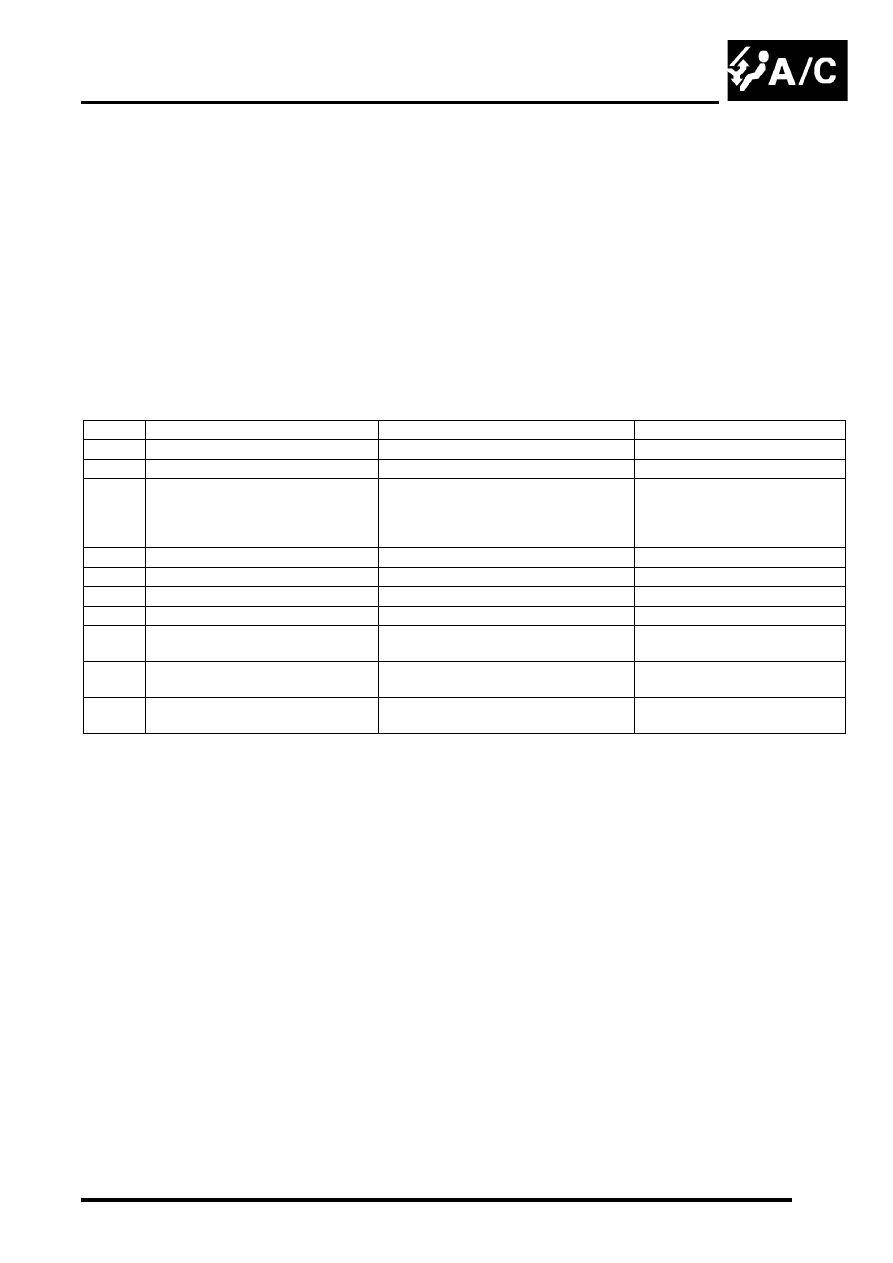
Diagnostic fault codes and fault descriptions
Code
Component
Fault
Default value/strategy
00
-
No fault found
-
11
In-car temperature sensor
Open or short circuit
25
°
C (77
°
F)
12
Ambient temperature sensor
Open or short circuit
10
°
C (50
°
F)
Cooling fan permanently on
Display shows "- -" if external air
temperature selected
13
Thermistor
Open or short circuit
0
°
C (32
°
F)
14
Heater coolant temperature sensor
Open or short circuit
70
°
C (158
°
F)
21
Sunlight sensor, left output
Open or short circuit
No solar heating correction
22
Sunlight sensor, right output
Open or short circuit
No solar heating correction
31
LH temperature servo motor
Open or short circuit
Motor or flap mechanism seized
Servo motor locked in position
32
RH temperature servo motor
Open or short circuit
Motor or flap mechanism seized
Servo motor locked in position
33
Distribution servo motor
Open or short circuit
Motor or flap mechanism seized
Servo motor locked in position