Discovery 2. Manual - part 139


  Index      Land Rover     Land Rover Discovery 2 - service manual 1999 year


Search            


Content   ..  137  138  139  140   ..


Discovery 2. Manual - part 139


TRANSFER BOX - LT230SE

OVERHAUL

41-59

20. Apply sealant, Part No. STC 50552 to bolt 

threads  fit housing to main case, fit bolts and 
tighten by diagonal selection to 45 Nm (33 
lbf.ft).

21. 03 Model Year onwards: Fit high/low selector 

fork and spring to high/low selector shaft, fit 
retaining clips.

CAUTION: Ensure ends of spring are fully 
seated in recess in clips.

22. Position high/low selector shaft and  fork to 

differential ensuring that fingers  of selector fork 
are located in selector  sleeve. 

23. Position differential assembly into  main casing 

ensuring that splines of rear  output shaft are 
engaged in differential. 

24. Position new differential front bearing  track 

ensuring that track is seated  squarely. 

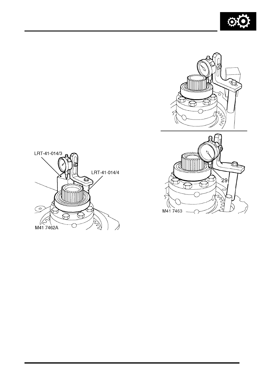
25. Position tool LRT-41-014/3 onto main  casing. 
26. Screw tool LRT-41-014/4 into tapped  hole in 

main casing and attach suitable DTI  to pillar. 

27. Position stylus of gauge to setting  block LRT-

41-014/3 and zero gauge. 

28. Position stylus onto front bearing outer track  

and record reading. 

29. Taking care not to disturb bearing, position 

stylus on opposite side of  bearing track and 
record reading. 

30. Obtain average of the 2 readings and  record 

figure. 

TRANSFER BOX - LT230SE

41-60

OVERHAUL

31. Position  depth  block tool LRT-41-014/2 and  

cross bar tool LRT-41-014/1 to  front output 
housing. 

32. Position DTI to tool LRT-41-014/1  cross bar 

and zero DTI on depth block. 

33. Position DTI to cross bar and record  reading 

obtained. 

34. Using the formula:  3.05 mm (0.120 in)+B-

A=D where:  B=Height difference recorded 
between depth  block and cross bar.  
A=Average of readings to differential front  
bearing outer track.  D=Thickness of shim 
required to give  differential bearing pre-load of 
0.05 mm  (0.002 in). 

35. From the resultant figure obtained,  select 

appropriate thickness shim from the  range 
available. 

36. Shims are available from 2.00 to 3.25 mm  

(0.08 to 0.13 in) thickness, rising in  increments 
of 0.05 mm (0.002 in). 

37. Heat the front output housing to  100

°

C (210

°

F) 

and fit new output  shaft bearing using tool 
LRT-41-011. 

38. Allow housing to air cool. 
39. Fit new bearing retaining circlip  ensuring that 

circlip is fully seated. 

40. Using tool LRT-41-012, fit new output  shaft oil 

seal. Check that oil seal is just  contacting 
circlip. 

CAUTION: Oil seal must be fitted dry.

TRANSFER BOX - LT230SE

OVERHAUL

41-61

41. Position selected shim in front output  housing 

and using tool LRT-54-003, fit new  differential 
front bearing track. 

42. Fit bearing spacer to output shaft with  chamfer 

on spacer towards threaded end. 

43.  If fitted: Fit dog clutch with flange on clutch  

facing towards splined end. 

44. Using a copper mallet, drive output  shaft into 

bearing. 

Note: Carry out the following operations for 
transfer boxes fitted with differential lock.

45. Compress differential lock selector  spring and 

fit selector fork. 

46. Position selector fork to groove in  dog clutch. 
47. Fit selector shaft and locate in housing  recess, 

rotate shaft until the two flats  for retaining clips 
are at right angles to  the cover plate mating 
face. 

48. Compress selector spring and fit  retaining clips 

at each end of spring. 

CAUTION: Ensure ends of spring are fully 
seated in recess of clips.

49. Apply sealant, Part No. STC 4600 to front  

output shaft housing. 

50. Position housing ensuring that output  shaft and 

dog clutch splines - if fitted  are correctly  
engaged. 

51. Clean output shaft housing bolt threads.
52. Apply sealant, Part No. STC 50552 to threads 

of bolts. 

53. Fit  output shaft housing bolts and tighten in a  

diagonal sequence to 45 Nm (33 lbf.ft).  

54. Apply sealant, Part No. STC 4600 to mating 

face of high/low selector housing.

55. Position high/low selector housing to front 

output housing ensuring that high/low selector 
finger is located in groove in selector shaft.

56. 03 Model Year onwards: Position multiplug 

and selector cable brackets to high/low selector 
housing

57. Apply sealant, Part No. STC 50552 to threads 

of selector housing bolts.

58. Up to 03 Model Year: Fit bolts  and tighten to 

25 Nm (18 lbf.ft).

59. Fit differential lock detent ball and spring. 
60. Apply sealant, Part No. STC 50552 to threads 

of differential lock detent  plug. 

61. 03 Model Year onwards - differential lock 

fitted: Fit and tighten detent plug, then  loosen 
2 complete turns. 

62. 03 Model Year onwards - differential lock 

fitted: Apply sealant, Part No. STC 50552 to 
threads of differential lock detent plug.

63. 03 Model Year onwards - differential lock 

fitted: Fit detent ball and spring.

TRANSFER BOX - LT230SE

41-62

OVERHAUL

64. 03 Model Year onwards - differential lock 

fitted: Fit differential lock detent plug and 
tighten until head of plug is level with face of 
output shaft housing.

65. 03 Model Year onwards - differential lock 

fitted: Using a straight edge, check that head 
of plug is correctly positioned, screw plug in or 
out as necessary.

66. 03 Model Year onwards - differential lock 

fitted: Lubricate and fit new 'O' rings to 
differential lock  selector housing. 

67. 03 Model Year onwards - differential lock 

fitted: Fit selector housing, ensure selector  
finger is located in shaft recess. 

68. 03 Model Year onwards: Position cable 

bracket to selector housing.

69.  Apply sealant, Part No. STC 50552 to threads 

of selector housing bolts, fit bolts and tighten to 
25 Nm (18 lbf.ft).

70. Up to 03 Model Year - differential lock fitted: 

Fit nut to differential lock warning lamp switch 
with counterbore positioned towards  switch 
head.  The nut acts as a spacer to ensure 
that  switch setting is correct. Always 
ensure that nut is fully tightened  to switch 
head (no gap).

71. Apply sealant, Part No. STC 50552 to threads 

of differential warning lamp switch.

72. Position switch into front output housing until 

nut bottoms  out on housing; tighten  nut to 11 
Nm (8 lbf.ft)

73. 03 Model Year onwards - differential lock 

fitted: Fit new aluminium sealing washers to 
differential lock warning lamp switches.

CAUTION: Ensure that replacement 
washers are the same thickness as the 
originals.

74. 03 Model Year onwards - differential lock 

fitted: Apply sealant, Part No. STC 50552 to 
threads of switches.

75. 03 Model Year onwards - differential lock 

fitted: Fit switches and tighten to 25 Nm (18 
lbf.ft).

76. Fit output flange, new felt washer,  steel washer 

and new retaining nut. 

M41 7886


Content   ..  137  138  139  140   ..