Discovery (1995+): Body Repair Manual - part 28


  Index      Land Rover     Discovery Body Repair Manual - 1995 year


Search            


Content   ..  26  27  28  29   ..


Discovery (1995+): Body Repair Manual - part 28


76

CHASSIS AND BODY

50

REPAIR

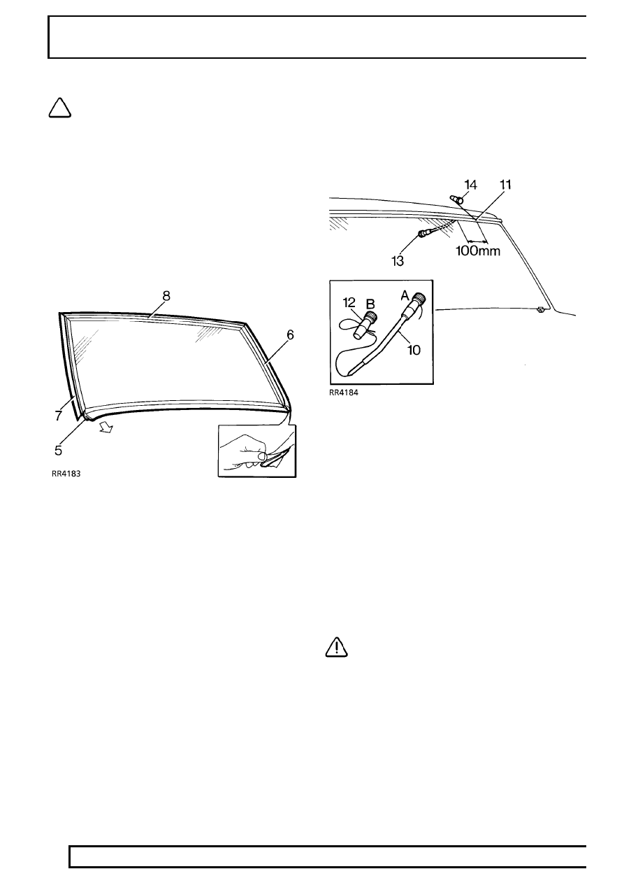
NOTE: If heated front screen: 2 electrical
multiplug connectors are located under
the decker [cowl] panel. To access release

decker panel.

Remove

1. Remove windscreen wiper arms.

See WIPERS

AND WASHERS, Repair.

2. Remove rear view mirror and stickers from

glass.

3. Remove ’A’ post finishers.
4. Fit protective cover over dash panel and apply

masking tape to protect ’A’ posts.

5. Ease one end of bottom finisher away from

glass, pull to disengage finisher flange and
remove.

6. Lift lip of LH ’A’ post finisher and release sealing

strip along its length, pull to disengage finisher
flange from glass and remove.

7. Remove RH ’A’ post finisher.
8. Remove header finisher.
9. Apply masking tape to protect paint finish around

glass.

10. Prepare cutting wire in handle ’A’. Bend end of

wire to handle and tape over end.

11. Force cutting wire through sealer from inside and

100mm (3 7/8 in) from a top corner. Use a
needle if necessary to make a pilot hole.

12. Attach handle ’B’. Allow 200mm (7 7/8 in) of wire

between handles, tape over end of wire.

13. With an assistant on the inside: Wedge the

tube of the handle ’A’ between glass and body
flange 100mm (3 7/8 in) ahead of hole in sealer.

14. From the outside: Carefully cut sealer from

flange using a straight pull away from the glass.
Continue in 100mm (3 7/8 in) steps around the
glass, use a sawing action at the corners.

CAUTION: Along the bottom edge, great
care must be taken to cut up to the 2
supports, positions indicated on the

obscuration band (See item 18).

15. Remove handle ’B’, withdraw the cutting wire

and insert it through the sealer between the
supports. Refit handle ’B’.

CHASSIS AND BODY

51

REPAIR

16. Cut through sealer between the supports.

If heated front screen: Cut through the 2 wires
each side of the supports. Tape cut wires and
panels to prevent damage to bodywork when
screen is removed.

17. Attach suction cups to glass and lift glass from

body flange, cut sealer free around supports as
necessary.

WARNING: If glass has splintered: Protect
eyes and operate demister blower at
maximum speed to remove any glass from

ducts. Use a vacuum cleaner to remove glass
particles from inside the vehicle.

Refit

18. Check condition of supports, renew if necessary.

Locating studs must be at right angle to flange.

NOTE: The supports were fitted to early
vehicles and now replaced with nylon
sheaths.

19. Carefully cut back old sealant around body

flange to obtain a smooth surface 2mm (1/10in)
thick. DO NOT cut down to flange.

20. If refitting original glass: It must be free from

chips or cracks. Cut back old sealant around
glass to obtain a smooth surface 2mm (1/10 in)
thick. DO NOT cut down to glass surface.

CAUTION: Lay glass on felt covered
supports, do not stand on edge. Any
chipping of glass edge may develop into

cracks.

21. Align header finisher on top edge of glass, push

flange fully onto glass and use a wooden block
and mallet to ensure fit.

22. Carefully align each side finisher on edge of

glass, push flange fully onto glass and use a
wooden block and mallet to ensure fit.

23. Using a cotton bud, apply glass cleaning solvent

(yellow cap) to inside face of glass, 20mm (13/16
in) strip around inside of finishers and 30mm (1
1/8 in) wide along bottom edge. Immediately
wipe off solvent with a clean cloth.

CAUTION: Do not touch cleaned or primed
surfaces with fingers.

76

CHASSIS AND BODY

52

REPAIR

24. Ensure body flanges and surfaces covered by

the finishers are clean.

25. Shake the primer container for at least 30

seconds.

26. Using a cotton bud, apply Glass Primer (green

cap) to inside face of glass, 20mm (13/16 in)
strip around inside of finishers and 30mm (1 1/8
in) wide along bottom edge. This must be touch
dry before applying adhesive.

27. Remove protective coverings and tape.

28. Pierce top and pre-cut nozzle to sealer cartridge,

remove lid and shake out crystals and install
cartridge in applicator gun.

29. Apply a continuous bead of adhesive sealant

around the glass as shown. Vertical edge of
sealer to abut finishers and to be 8mm (5/16 in)
from bottom edge of glass.

30. Remove protective covering (RED) from side

finisher sealing strip.

CHASSIS AND BODY

53

REPAIR

31. With assistance: Attach suction cups to glass

and lift into position, carefully align the indicators
on the obscuration band with the supports.
Lower screen onto body flange, check alignment
and firmly press to seat glass in the aperture.

NOTE: The finisher on later vehicles will
not have cutouts, or supports fitted, as
shown.

32. Align cut outs with the supports and push

finisher fully onto the glass. Use a wooden block
to ensure fit.

33. Refit ’A’ post finishers and interior mirror.
34. Refit wiper arms.

FRONT SEAT - ELECTRIC

Service repair no - 76.77.01

Remove

1. Operate controls to adjust seat fully backwards

and remove 2 bolts securing seat slides.

2. Operate controls to adjust seat fully forwards.

3. Remove 3 studs securing seat side valance.
4. Remove side valance.


Content   ..  26  27  28  29   ..