Index Land Rover Land Rover Discovery - service 1995-1996 year
Search
Content .. 221 222 223 224 ..
Land Rover Discovery. Manual - part 223
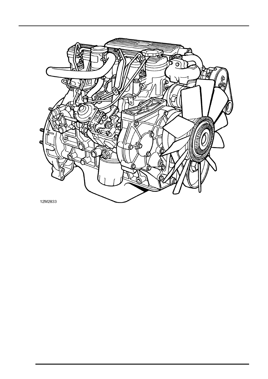
ENGINE
14
DESCRIPTION AND OPERATION